Method for controlling motion of cylinder piston of piston engine and device for implementing method

A technology of piston engine and engine cylinder, applied in the direction of internal combustion piston engine, engine cooling, mechanical equipment, etc., can solve the problems of engine consumption, easy wear, and large fuel loss, achieve high-efficiency, high-temperature and high-pressure combustion air, and prolong engine life. , significant effect of energy saving and emission reduction

Inactive Publication Date: 2012-03-28
李永红
View PDF6 Cites 0 Cited by
  • Summary
  • Abstract
  • Description
  • Claims
  • Application Information

AI Technical Summary

Problems solved by technology

Disadvantages of two-stroke engines: the intake and exhaust process takes a short time, so the fuel loss is large and the environmental pollution is large; there is an air port on one side of the cylinder wall, and the piston ring is easy to wear when it comes into contact with it; since the exhaust port is on the cylinder, it is easy to overheat
Disadvantages of the four-stroke engine: the engine burns once every two weeks of crankshaft rotation, so the rotation balance is unstable and the mechanical noise is large; the three-stroke intake, compression, and exhaust are all driven by the work done by the engine; the pursuit of high compression ratio and There is a great contradiction between the spontaneous combustion of fuels, which requires many means to resolve; the exhaust gas is also more serious to the environmental pollution
Among them, the turbocharger has too high requirements on the manufacturing materials and coolant due to the working environment factors, and it is often accompanied by hysteresis during the working process. It also transmits the force to the engine piston through the exhaust gas, which causes another part of useless work while saving energy; the supercharger uses the engine as the power source and consumes the work done by the engine.

Method used


Image

  • Method for controlling motion of cylinder piston of piston engine and device for implementing method
  • Method for controlling motion of cylinder piston of piston engine and device for implementing method
  • Method for controlling motion of cylinder piston of piston engine and device for implementing method

Examples


Embodiment 1

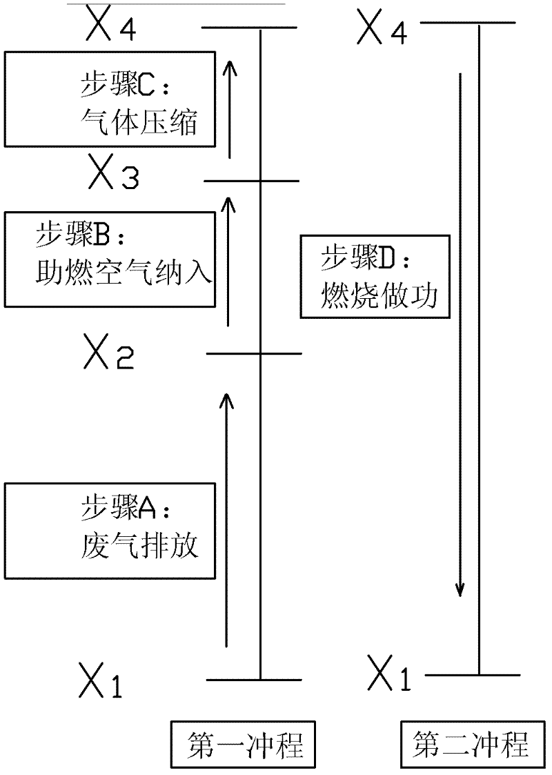
[0034] This embodiment provides a method for controlling the motion of the cylinder piston of a piston engine. The process is as follows: image 3 As shown, the engine cylinder has an intake valve, an exhaust valve and a combustion chamber, and the piston moves up and down driven by the crankshaft (the piston drives the crankshaft to rotate during the working stroke), and the piston runs in the cylinder with a bottom dead center X1 and a top dead center X4 , the intake valve is connected to the high-temperature and high-pressure combustion air source through the intake pipe, and two dead centers are added between the bottom dead center X1 and the top dead center X4, which are divided into the first dead point X2 and the second dead point X3, and the second The stop point X3 is above the first stop point X2, and the piston movement is controlled according to the following steps:

[0035] Step A, the exhaust valve is opened, the intake valve is closed, the piston moves upward fr...

Embodiment 2

[0045] This embodiment provides another device for obtaining high-temperature and high-pressure combustion-supporting air. The structure of this embodiment is the same as that of Embodiment 1, except that the specific height (distance perpendicular to the ground) of some parts is limited, specifically: the same pressure pipe 15 has a first steam flow port 13 located on the high temperature and high pressure steam generator 2 and a second steam flow port 16 located on the liquid storage and infusion tank 20; vertically speaking, the first steam flow port 13 is located on the high temperature and high pressure steam generator 2 The highest point of the internal space, the second steam circulation port 16 is located at the highest point of the internal space of the liquid storage and infusion tank 20, the highest point of the internal space of the high-temperature and high-pressure steam generator 2 is higher than the highest point of the internal space of the liquid storage and in...

Embodiment 3

[0047] This embodiment is a method for controlling the movement of the cylinder piston of a piston engine. The control process is the same as that of Embodiment 1. The high temperature and high pressure combustion air of this embodiment is obtained by using an existing turbocharger or supercharger. The high-pressure air delivery pipe 8 communicates with the turbocharger or supercharger and the high-temperature and high-pressure air storage tank 5, and then guides it into each combustion chamber of the engine through the intake branch pipe 6, thereby omitting other components.


PUM


Abstract

The invention belongs to the technical field of engine control, and relates to a method for controlling the motion of a cylinder piston of a piston engine and a device for implementing the method. The motion of the piston is controlled through the following steps that: A, a piston moves from a bottom dead center X1 to a position X2 upwards under the driving of a crankshaft, an exhaust valve is opened, an inlet valve is closed, and waste gas is discharged from a gas outlet; B, when the piston arrives at the position X2, the inlet valve is opened, the exhaust valve is closed, high-temperature and high-pressure combustion-supporting air is fed from the inlet valve, and the piston continues to move upwards to a position X3; C, when the piston arrives at the position X3, the inlet valve and the exhaust valve are both closed, and the piston continues to move to a top dead center X4; and D, the inlet valve and the exhaust valve are both closed, mixed gas is combusted so as to act on the piston, and the piston moves from the top dead center X4 to the bottom dead center X1. By using the method and device disclosed by the invention, under same conditions, compared with two-stroke engines and four-stroke engines, larger power, higher stability, lower noise and more significant energy saving and emission reduction can be obtained.

Description

technical field [0001] The invention belongs to the technical field of engine control, and relates to a method for controlling the motion of a cylinder piston of a piston engine and equipment for realizing the method. Background technique [0002] At present, piston engines are divided into two-stroke and four-stroke. There are three holes on the cylinder block of the two-stroke engine, namely the air intake hole, the exhaust hole and the ventilation hole. These three holes are closed by the piston at a certain moment. , two-stroke engine cylinder piston movement as figure 1 As shown, it is specifically: (1) The first stroke: the piston moves upward from the bottom dead center X1, and after the three air holes are closed at the same time, the mixed gas entering the cylinder is compressed, and when the air intake hole is exposed, the combustible mixed gas flows into the crankcase; (2) The second stroke: when the piston is compressed to the vicinity of the top dead center X4,...

Claims


Application Information

Patent Timeline
Patent Type & Authority Applications(China)
IPC IPC(8): F02B47/02F02B41/00F02B33/40F02B39/04F02M25/032F01N5/02F22B1/18F01P3/22
CPCY02T10/16Y02T10/121Y02T10/12
Inventor 李永红
Owner 李永红
Why Eureka
Try Eureka