Passive gas imaging system

A gas imaging and passive technology, applied in the field of infrared thermal imaging, can solve the problems of low cost and need a laser light source, and achieve the effects of cost reduction, simple coating process and volume reduction

Inactive Publication Date: 2012-03-28
北方广微科技有限公司
View PDF5 Cites 19 Cited by
  • Summary
  • Abstract
  • Description
  • Claims
  • Application Information

AI Technical Summary

Problems solved by technology

[0008] A laser imaging SF is disclosed in Chinese utility model patent 200820167479.8 6 The gas leak location system integrates the laser and the thermal imaging camera in

Method used


Image

  • Passive gas imaging system
  • Passive gas imaging system
  • Passive gas imaging system

Examples


Embodiment Construction

[0024] In order to make the object, technical solution and advantages of the present invention clearer, the embodiments of the present invention will be described in detail below with reference to the accompanying drawings.

[0025] Embodiments of the present invention are described in detail below, examples of which are shown in the drawings, wherein the same or similar reference numerals designate the same or similar elements or elements having the same or similar functions throughout. The embodiments described below by referring to the figures are exemplary only for explaining the present invention and should not be construed as limiting the present invention.

[0026] The following disclosure provides many different embodiments or examples for implementing different structures of the present invention. To simplify the disclosure of the present invention, components and arrangements of specific examples are described below. Of course, they are only examples and are not int...


PUM


Abstract

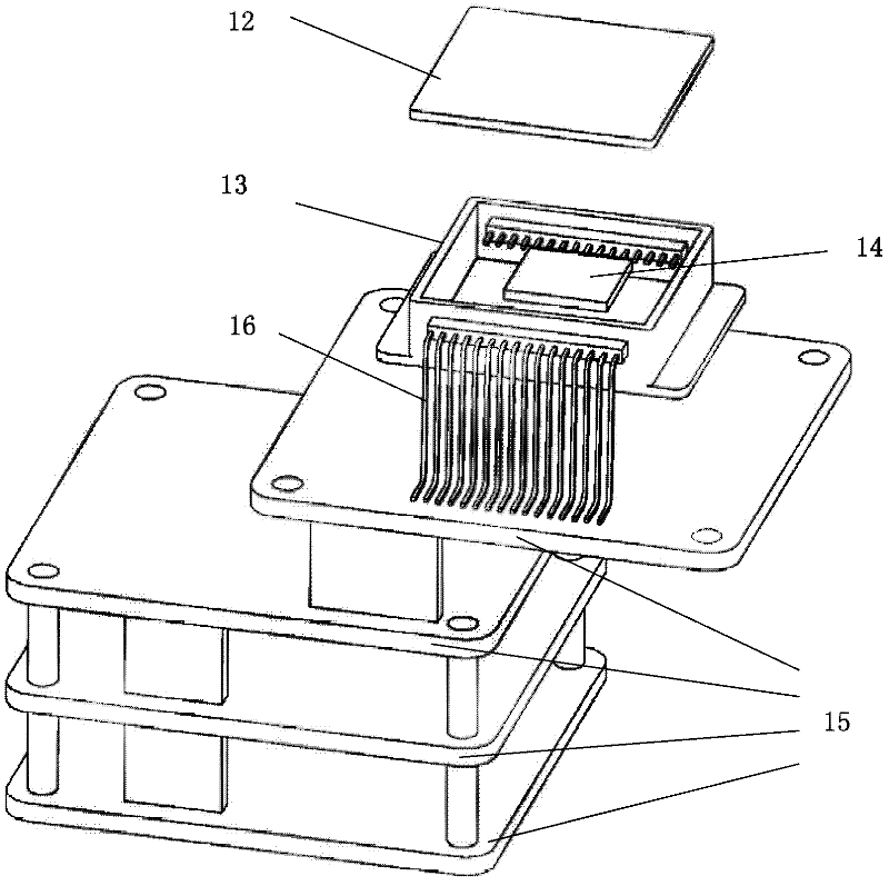
The invention provides a passive gas imaging system, which comprises an infrared imaging system, a visible light imaging unit, a central processing unit and a display, and is characterized in that: the front end of the infrared imaging unit is provided with an infrared optical lens; the front end of the visible light imaging unit is provided with a visible light optical lens; output signals of the infrared imaging unit and the visible light imaging unit are connected with the central processing unit; the central processing unit is used for processing signals and overlapping a processed infrared image with a processed visible image; the display is connected with the output of the central processing unit, and is used for displaying an output result; the infrared imaging unit comprises an infrared light window, a tube shell, a non-refrigerating infrared focal plane array chip and an infrared imaging digital signal processing circuit board; the infrared light windows is provided with an infrared narrowband optical filter; and the penetration wavelength is equal to the absorbing wavelength of a gas to be detected. The passive gas imaging system is convenient to carry; and a laser is not required, so that the equipment size is reduced, and the cost is lowered.

Description

technical field [0001] The invention belongs to the technical field of infrared thermal imaging, in particular to a passive gas imaging system based on uncooled infrared focal plane technology. Background technique [0002] In the power industry, daily chemical industry, and petrochemical industry, various gases are used, so it is often necessary to measure gas leakage or gas concentration. For colored and odorous gases, the location and severity of leaks can be qualitatively judged by vision or smell, but for colorless and odorless gases, instruments must be used for measurement. When the leakage point is known, the gas concentration can be easily measured with the corresponding gas sensor. However, since the gas itself is colorless and odorless, if the user does not know where the leak is in advance, the gas sensor cannot be used to determine the location of the leak. [0003] Passive gas imaging technology based on infrared focal plane technology is an indirect method t...

Claims


Application Information

Patent Timeline
IPC IPC(8): G01N21/35G01N21/3504
Inventor 方辉雷述宇
Owner 北方广微科技有限公司
Why Eureka
Try Eureka