Real-time monitoring system of driver working state

A technology for real-time monitoring system and working status, applied in the field of monitoring system, can solve the problems of not being a locomotive attendant, preventing and reminding in time, abnormal section occupancy signals, and obstacles, etc., so as to eliminate the interference of sunglasses, eliminate the interference of light, and reduce the interference. Effect

Active Publication Date: 2012-03-28
SHANXI ZHIJI ELECTRONICS TECH
View PDF4 Cites 29 Cited by
  • Summary
  • Abstract
  • Description
  • Claims
  • Application Information

AI Technical Summary

Problems solved by technology

The characteristic of these methods is that they are mandatory. Although they are effective, they are still not a precautionary measure and a timely reminder to the locomotive crew when they are not working.
Moreover, the locomotive crew is in a state of no monitoring for as long as 2 minutes on the high-speed train, which has major safety hazards and safety management blind spots
[0004] At present, the running speed of some trains has reached 160km / h, about 2640 meters per minute; the running speed of high-speed rail EMUs has reached 350km / h, about 5820 meters per minute, and the existing unmanned vigilance device is not monitoring during these 2 minutes During the period, once the locomotive crew members doze off during this period; lookout intermittently, coupled with unexpected situations such as obstacles in the operating section, abnormal section occupancy signals, etc., must constitute a lookout accident

Method used


Image

  • Real-time monitoring system of driver working state
  • Real-time monitoring system of driver working state
  • Real-time monitoring system of driver working state

Examples


Embodiment Construction

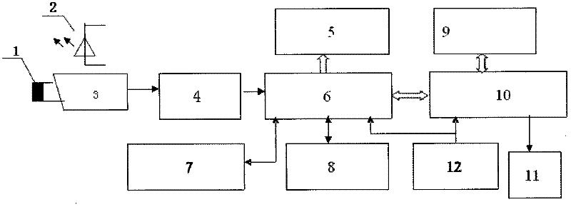
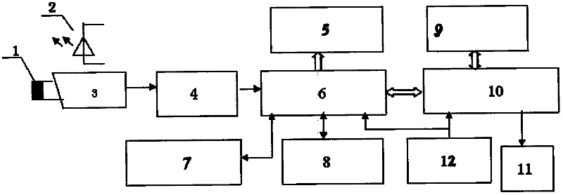
[0023] Below by embodiment, and in conjunction with accompanying drawing, the present invention will be further described:

[0024] A real-time monitoring system for the driver's working state, which includes a band-pass filter 1, an infrared active light source 2, a CCD camera 3, a video decoder 4, a voice alarm 5, an image preprocessor 6, an image memory 7, and an alarm image memory 8 , program memory 9, multimedia digital memory 10, 100M network port 11 and zero speed processor 12, CCD camera 3 is provided with a band-pass filter 1, infrared active light source 2 is arranged above the CCD camera 3, CCD camera 3 and video decoding Device 4 is connected, video decoder 4 is connected with image preprocessor 6, and image preprocessor 6 is respectively connected with voice alarm 5, image processor 7, warning image processor 8, multimedia digital storage 10, and multimedia digital storage 10 is respectively It is connected with the program memory 9 and the 100M network port 11, a...


PUM


Abstract

The invention relates to a real-time monitoring system of a driver working state. The real-time monitoring system is characterized in that a band-pass filter (1) is arranged on a CCD (charge-coupled device) camera (3); an infrared active light source (2) is arranged above the CCD camera (3); the CCD camera (3) is connected with a video decoder (4); the video decoder (4) is connected with an imagepre-processor (6); the image pre-processor (6) is respectively connected with a voice alarm (5), an image processor (7), an alarming image processor (8) and a multimedia digital memory (10); the multimedia digital memory (10) is respectively connected with a program memory (9) and a 100M network interface (11); and a zero-speed processor is respectively connected with the multimedia digital memory (10) and the image pre-processor (6). According to the real-time monitoring system, real-time monitoring to working states of locomotive drivers under the conditions of different driving postures, different lighting status, wearing glasses and sunglasses and the like can be achieved, and voice alarm prompt is provided when the locomotive drivers intermittently watch outside or nap.

Description

technical field [0001] The invention belongs to a monitoring system, in particular to a real-time monitoring system for the working state of train or automobile drivers. Background technique [0002] With the rapid development of railways and high-speed railways being put into operation, people pay more and more attention to the safety of train operation. In order to ensure the safety of train operation, the railway department stipulates that the locomotive crew should keep an eye on the running direction of the train during the running of the train. At present, locomotives are pulling cross-roads, long-distance cross-sections and cross-office round trips are implemented. The operation section is long and single-post operations are prone to lack of concentration and intermittent observation due to fatigue. Accidents caused by this are sometimes occur. Therefore, it is very practical and necessary to develop a device that can effectively and in real time monitor whether the...

Claims


Application Information

Patent Timeline
Patent Type & Authority Applications(China)
IPC IPC(8): G08B21/00G08B21/06G06K9/00B61C17/00
Inventor 安永琳杨荣国江国强杨李成
Owner SHANXI ZHIJI ELECTRONICS TECH
Why Eureka
Try Eureka