Novel conducting wire end ground clip

A technology of grounding clamps and wire ends, which is applied in the direction of conductive connection, connection, and electrical component connection, which can solve the problems of high labor intensity, difficult operation, and loss of protection, etc., to reduce labor intensity, reduce the number of spiral turns, and facilitate construction and operation Effect

Inactive Publication Date: 2012-03-28
ELECTRIC POWER RES INST OF GUANGXI POWER GRID CO LTD
View PDF7 Cites 31 Cited by
  • Summary
  • Abstract
  • Description
  • Claims
  • Application Information

AI Technical Summary

Problems solved by technology

However, for the 500kV line, the first three types of clip structures are not reasonable, and they are easy to fall off, making the working point lose protection
Although the spiral type can ensure reliable ground

Method used


Image

  • Novel conducting wire end ground clip
  • Novel conducting wire end ground clip
  • Novel conducting wire end ground clip

Examples


Embodiment Construction

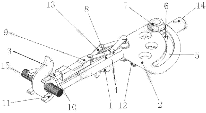
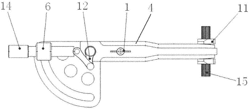
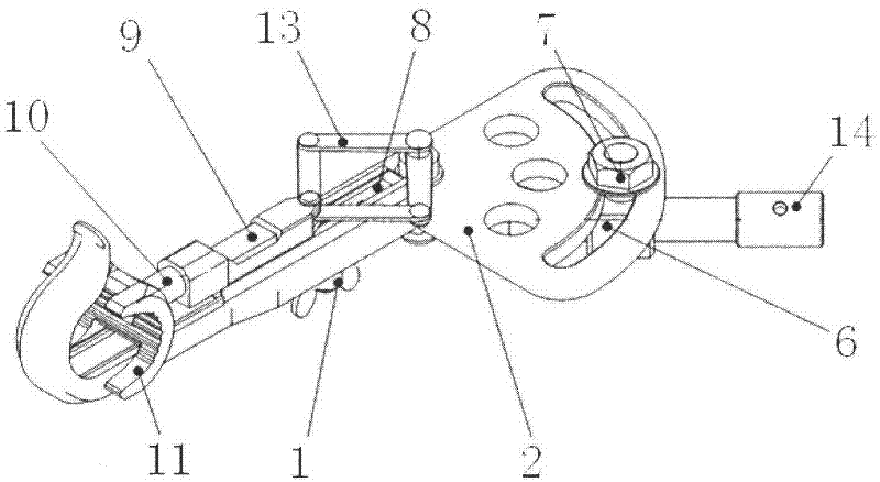
[0016] Such as Figure 1 to Figure 7 As shown, the novel wire end grounding clamp of the present invention comprises a clamp main body, an auxiliary clamp, a joystick 14 and a transmission mechanism. One end of the clamp main body is a fan-shaped plate 2 with a central angle of 90 degrees, and the other end is a main wire chuck 3. The middle is connected by the clip body 4, the fan-shaped plate 2 is provided with an arc limit groove 5, the top of the clip body 4 is fixedly installed with a chute 8 along the axial direction, and the bottom of the clip body 4 is provided with a ground wire connector 1; Including the auxiliary line clamp 11 and the push rod slider 9, the auxiliary line clamp 11 is connected to one end of the length adjustment screw 10 through the rotation pair, and the other end of the length adjustment screw 10 is connected to the push rod slider 9 through threads, so the length can be adjusted by controlling the The screw rod 10 is screwed into the length of th...


PUM


Abstract

The invention discloses a novel conducting wire end ground clip, which comprises a wire clip main body, an auxiliary wire clip, a control lever and a driving mechanism. By combining and using the control lever, a crank link mechanism and a scissors mechanism, the chuck stroke of the wire clip is amplified to fulfill the aim of reducing the spiral circles and reducing the labor intensity. A chuck can be opened and closed by only rotating the control lever so that clamping and loosening actions of a high-voltage cable are quickly finished. With the innovation, the problem of overmany rotating circles of a wire clip of the conventional pure screw rod mechanism is solved, so that construction operation is simpler and more convenient, and the workload of detection personnel can be effectively reduced. Besides, the novel conducting wire end ground clip meats the requirement of adjustable angle between the wire clip and the control level by using an angle adjustment positioning bolt and an arc limiting slot of a sector plate.

Description

technical field [0001] The invention relates to a high-voltage wire detection tool, in particular to a novel wire end grounding clamp. Background technique [0002] The grounding clamp at the wire end is a safety device used to temporarily short-circuit and ground the power-off transmission wire. Its function is to prevent the harm to the human body caused by the sudden incoming power or the induced voltage generated by the adjacent high-voltage live equipment during the maintenance of the high-voltage transmission wire. At present, the clamps used by various power grid companies mainly include double tongue type, flat type, impact type and spiral type. However, for the 500kV line, the first three types of clip structures are not reasonable, and they are easy to fall off, making the working point lose protection. Although the spiral type can ensure reliable grounding, the use of it is labor-intensive, inefficient, and difficult to operate, and it is easy to cause constructi...

Claims


Application Information

Patent Timeline
IPC IPC(8): H01R11/14H01R4/28
Inventor 许飞王凯郑广平陈渊汪丽川周柯李岩舟冯文昕
Owner ELECTRIC POWER RES INST OF GUANGXI POWER GRID CO LTD
Why Eureka
Try Eureka