Micro drill and manufacturing method thereof

A micro drill bit and manufacturing method technology, applied in the direction of manufacturing tools, drill repairing, drilling tool accessories, etc., can solve the problems of large frictional resistance, poor hole thickness, poor positioning performance, etc., to improve cutting efficiency, improve positioning performance, cutting edge The effect of length reduction

Inactive Publication Date: 2012-04-04
SHENZHEN JINZHOU PRECISION TECH
View PDF9 Cites 7 Cited by
  • Summary
  • Abstract
  • Description
  • Claims
  • Application Information

AI Technical Summary

Problems solved by technology

The 129 drill bit has a drill point, and the two chisel edges form an obtuse angle at the drill point. When the drill bit is processing the workpiece, a single drill point enters the drill, and the positioning performance is poor. During the drilling process, the PCB glass fiber cloth is crisscrossed and uneven The surface of the drill bit is subjected to the impact of lateral force, resulting in a decrease in the accuracy of the drilling hole and poor hole thickness; while the 131 chisel edge is a straight line segment, the chisel edge is long and the main cutting edge is short, the friction resistance is large when the drill is processed, and the wear Serious, and the 131 drill bit has a diameter of more than 3mm, which is not suitable for processing micro-apertures

Method used


Image

  • Micro drill and manufacturing method thereof
  • Micro drill and manufacturing method thereof
  • Micro drill and manufacturing method thereof

Examples


Embodiment 1

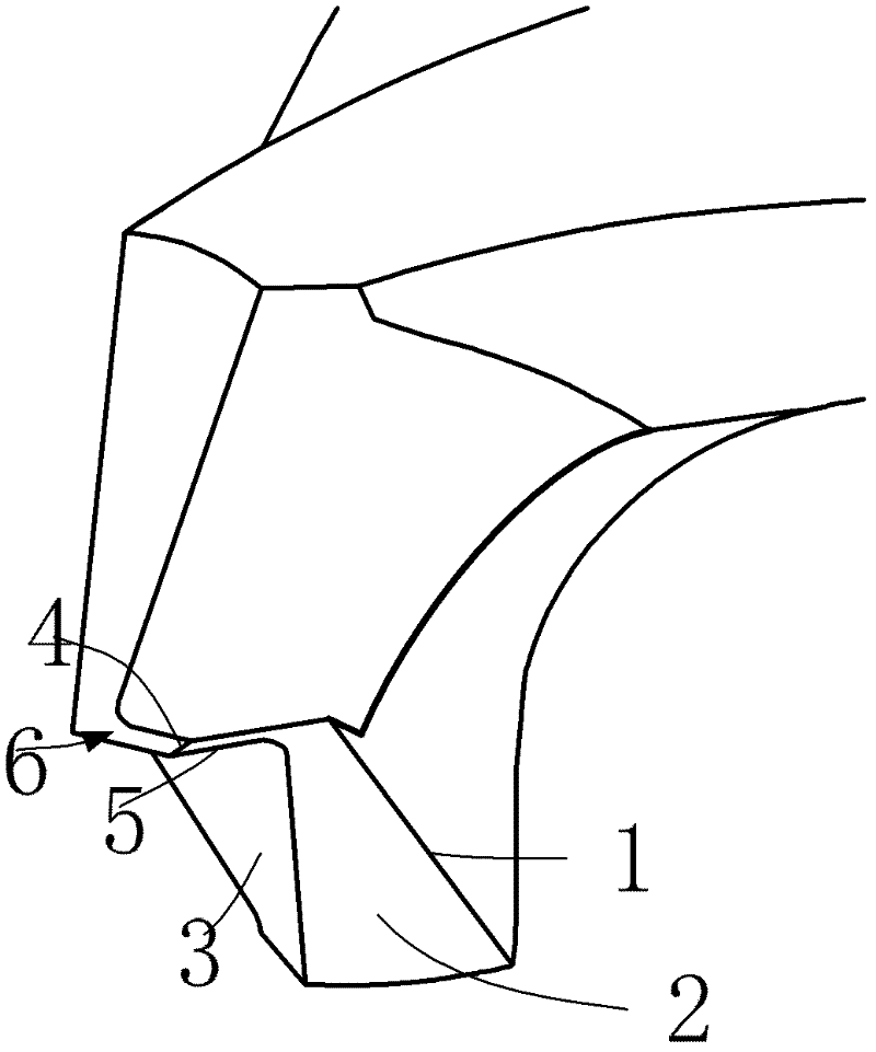
[0042] Embodiment one, such as Figure 1~5 Shown:

[0043] A micro drill, comprising two main cutting edges 1, each main cutting edge is provided with a first relief surface 2 and a second relief surface 3, the first relief surface 2 and the second relief surface The intersection line of surface 3 deviates from the position of the drill bit axis. The two first flanks 2 extend toward the axis of the drill bit to form two core cutting surfaces 6. The core cutting surfaces 6 intersect at the axis of the drill to form a chisel edge 4. The two core cutting surfaces 6 The side intersecting with the main cutting edge 1 forms two drill core edges 5 for cutting. The width of the chisel edge 4 is obliquely intersected with the core edge 5 of the drill point; the projections of the straight lines where the two main cutting edges are located on the cutting plane are parallel to each other.

[0044] In the present invention, the chisel edge 4 may also be perpendicular to the core edge 5...

Embodiment 2

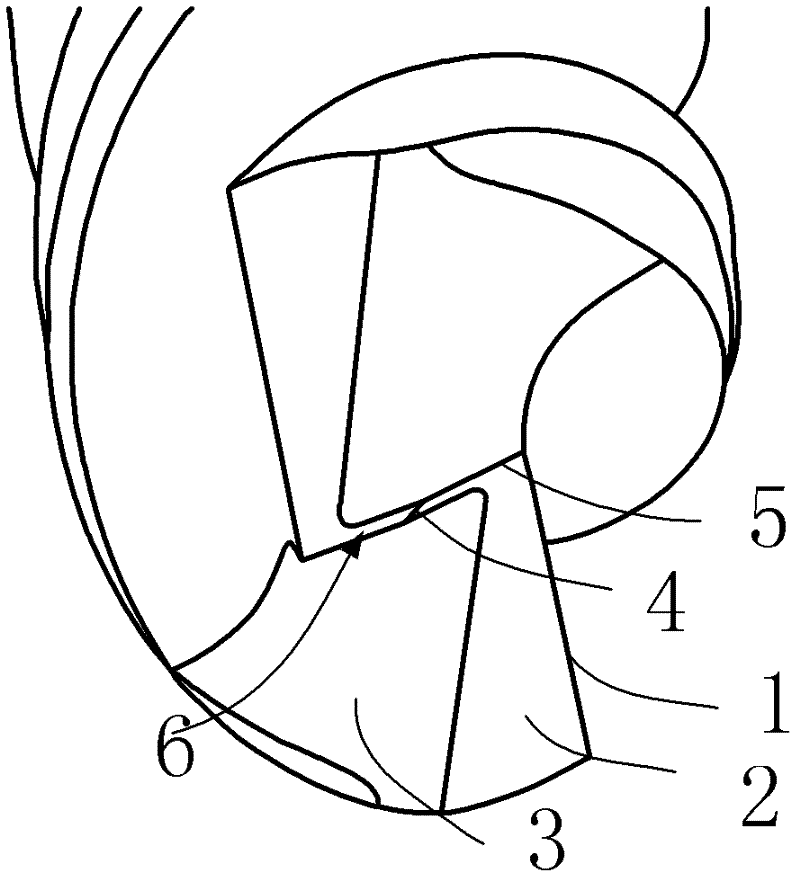
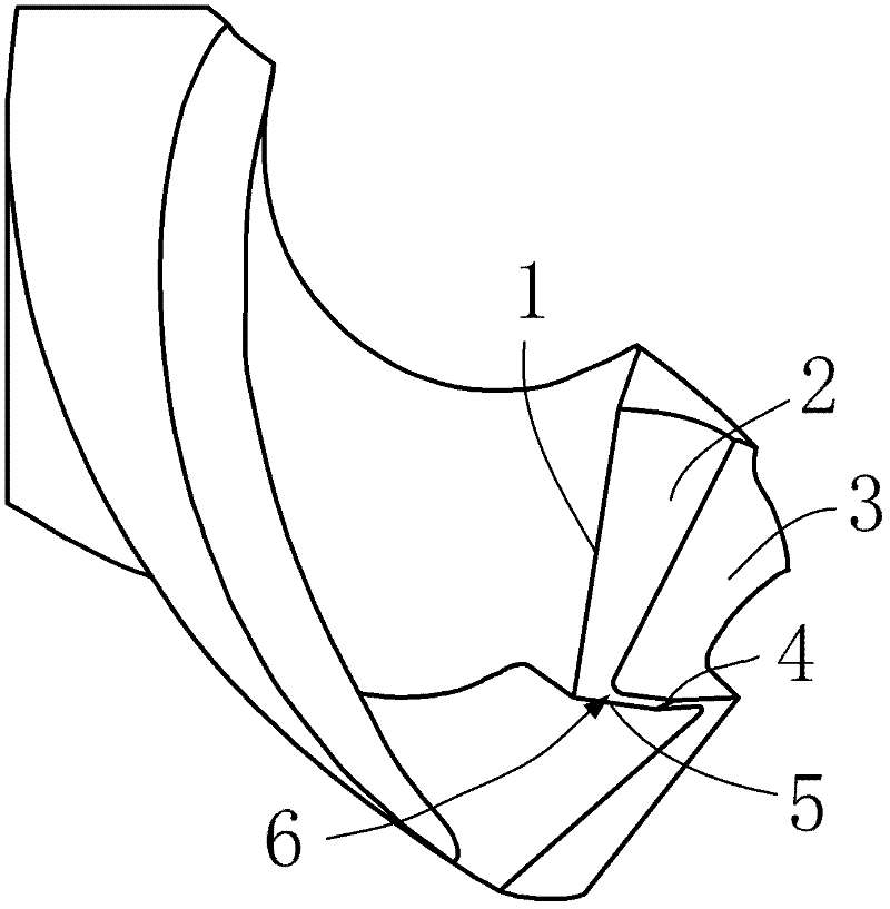
[0045] Embodiment two, such as Figures 6A-14 Shown:

[0046] A micro drill, comprising two main cutting edges 1, each main cutting edge is provided with a first relief surface 2 and a second relief surface 3, the first relief surface 2 and the second relief surface The intersection line of surface 3 deviates from the position of the drill bit axis. The two first relief surfaces 2 extend toward the drill bit axis to form two core cutting surfaces 6. The core cutting surfaces 6 intersect at the drill bit axis to form a chisel edge 4. The core cutting surfaces 6 and the The intersecting side of the main cutting edges 1 forms a drill core edge 5 for cutting. The width of the chisel edge 4 is obliquely intersected with the core edge 5 of the drill point; the projections of the straight lines where the two main cutting edges are located on the cutting plane intersect.

[0047] In the present invention, the chisel edge 4 may also be perpendicular to the core edge 5 of the drill p...

Embodiment 3

[0050] A micro-drill, comprising two main cutting edges 1, each of the main cutting edges is provided with a relief surface, and the two relief surfaces are provided with two core cutting edges intersecting at the axis of the drill bit at the intersection The core cutting surface 6 intersects at the axis of the drill bit to form a chisel edge 4 , and the side where the core cutting surface 6 intersects with the main cutting edge 1 forms a drill point core cutting edge 5 . The width of the chisel edge 4 is arranged obliquely and intersecting with the core edge 5 of the drill point.

[0051] In the present invention, the chisel edge 4 may also be perpendicular to the core edge 5 of the drill point. Drilling through the chisel edge 4, if the chisel edge 4 is too long, it will increase the drilling resistance and increase the wear of the drill bit; however, the material of the drill bit is not rigid enough, and the chisel edge 4 that is too short will cause too much stress to conc...


PUM


Abstract

The invention discloses a micro drill and a manufacturing method thereof. A micro drill comprises two main cutting edges, each main cutting edge being correspondingly provided with a major first flank and a major second flank, which are characterized in that the intersecting line of the major first flank and the major second flank deviates from the axial position of the drill; two said flank faces extend to the drill axial position to form two core edge faces, the core edge faces intersecting at the drill axial position to form chisel edge which is a line segment, and two drill tip core edges are formed on the side that the two core edge faces intersect with the corresponding main cutting edges. The invention improves cutting efficiency, lessens wear on the drill, and also can improve the positioning performance of the drill.

Description

technical field [0001] The invention relates to the field of machining, and more specifically, relates to a micro drill bit and a manufacturing method thereof. Background technique [0002] PCB circuit boards need to be drilled with micro-drills in the process of processing. With the trend of miniaturization of electronic products, the area of ​​circuit boards with the same function is gradually reduced, and the processed aperture is also shrinking, which puts higher demands on the processing technology. Require. Common PCB micro-drills in the prior art include 129 drill bits and 131 drill bits. The 129 drill bit has a drill point, and the two chisel edges form an obtuse angle at the drill point. When the drill bit is processing the workpiece, a single drill point enters the drill, and the positioning performance is poor. During the drilling process, the PCB glass fiber cloth is crisscrossed and uneven The surface of the drill bit is subjected to the impact of lateral forc...

Claims


Application Information

Patent Timeline
Patent Type & Authority Applications(China)
IPC IPC(8): B23B51/00B23P15/28
Inventor 郭强付连宇
Owner SHENZHEN JINZHOU PRECISION TECH
Why Eureka
Try Eureka