Lamination buffering device for permanent magnet rotor of neodymium-iron-boron permanent magnet synchronous motor

A permanent magnet synchronous, permanent magnet rotor technology, applied in the direction of electromechanical devices, manufacturing motor generators, electric components, etc., can solve the problems of lack of buffer, aggravated silicon steel sheet offset, silicon steel sheet offset and other problems, to improve the lamination effect , reduce the offset, prolong the effect of the force process

Pending Publication Date: 2019-11-08
JIANGXI SENYANG TECH
View PDF0 Cites 1 Cited by
  • Summary
  • Abstract
  • Description
  • Claims
  • Application Information

AI Technical Summary

Problems solved by technology

[0003] The difference between the permanent magnet synchronous motor and the ordinary asynchronous motor is the rotor structure. The permanent magnet poles are installed on the rotor. The permanent magnet rotor core still needs to be stacked with silicon steel sheets. The protruding permanent magnet rotor only has a hole in the center. Now In the prior art, the silicon steel sheet is prone to deflection when the silicon steel sheet is laminated, and in the prior art, the indenter directly contacts the silicon steel sheet, and the pressure on the silicon steel sheet reaches the maximum momentarily, and the lack of buffering exacerbates the deflection of the silicon steel sheet. shift

Method used


Image

  • Lamination buffering device for permanent magnet rotor of neodymium-iron-boron permanent magnet synchronous motor
  • Lamination buffering device for permanent magnet rotor of neodymium-iron-boron permanent magnet synchronous motor
  • Lamination buffering device for permanent magnet rotor of neodymium-iron-boron permanent magnet synchronous motor

Examples


Embodiment 1

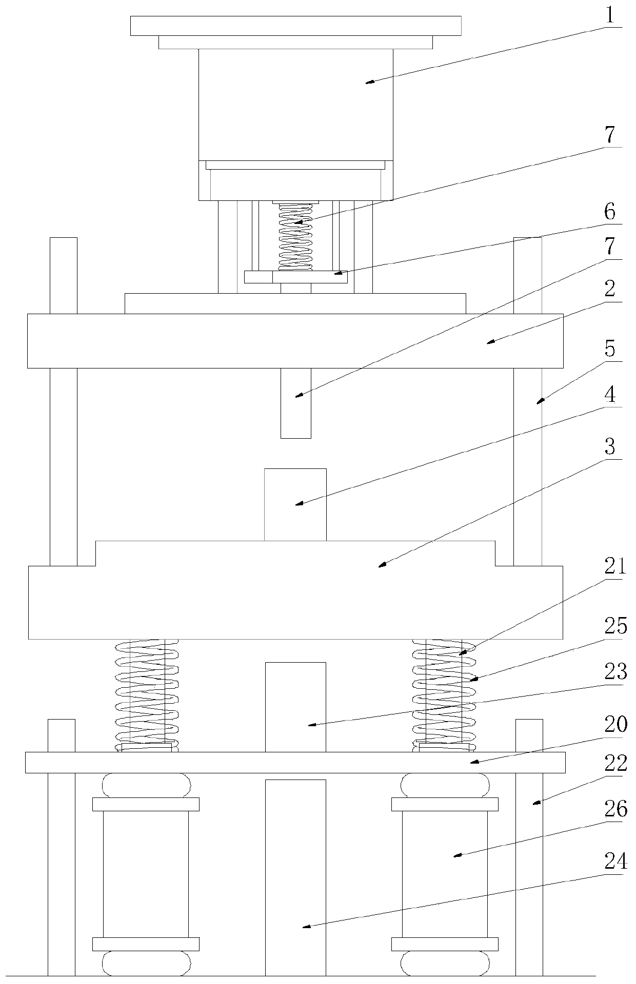
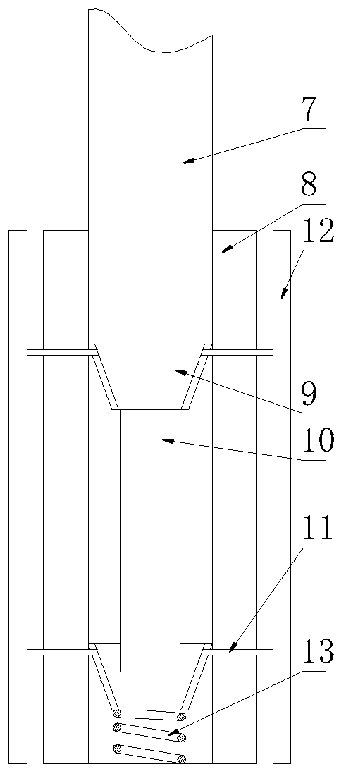
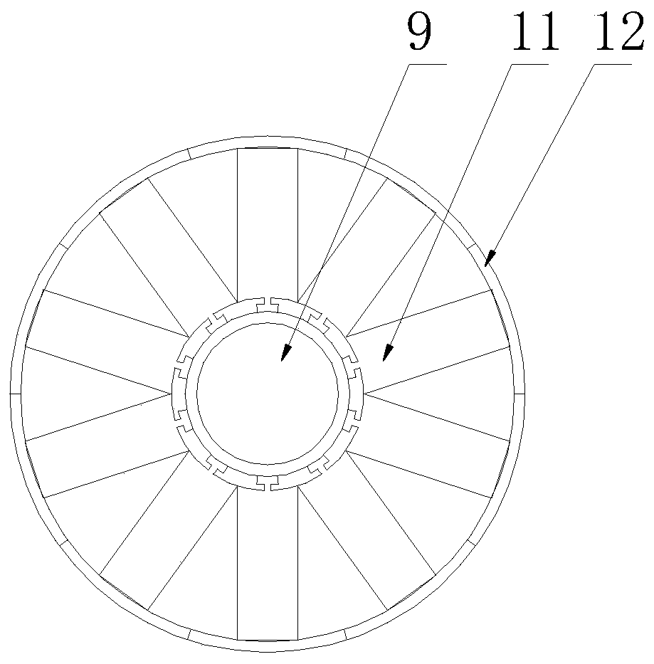
[0023] See Figure 1-4 In the embodiment of the present invention, a buffer stacking device for a permanent magnet rotor of a Ru-Fe-B permanent magnet synchronous motor includes an indenter 1, an upper sliding seat 2, a lower seat 3, an outward expansion mechanism 4 and a secondary buffer mechanism, The indenter 1 is arranged on the top of the upper sliding seat 2, a sliding seat 3 is arranged under the upper sliding seat 2, an outward expansion mechanism 4 is arranged at the top center of the lower sliding seat 3, and four sliding seats are arranged on the top of the sliding seat 3 The guide rod 5, the slide seat guide rod 5 penetrates the four corners of the upper slide seat 2, and the upper slide seat 2 is provided with through holes that are clearance fit with the slide seat guide rod 5;

[0024] The bottom of the indenter 1 is connected to the top of the upper slide 2 through several connecting rods. A small pressure plate 6 is arranged between the several connecting rods. T...


PUM


Abstract

A lamination buffering device for a permanent magnet rotor of a neodymium-iron-boron permanent magnet synchronous motor comprises a pressure head, an upper sliding base, a lower sliding base, an external expansion mechanism and a second-stage buffer mechanism. The pressure head is arranged on the top of the upper sliding base; the lower sliding base is arranged under the upper sliding base; and the top center of the lower sliding base is provided with the external expansion mechanism. The external expansion mechanism comprises a cylindrical body, conical heads, a pressure rod, push pieces, external expansion pieces and a reset spring. The second-stage buffer mechanism comprises a buffer base, a first-stage buffer guide rod, a second-stage buffer guide rod, a first-stage limit column, a second-stage limit column, a buffer spring and a buffer rubber column. Through cooperation of a punch rod and the external expansion mechanism, limit of multilayer silicon steel sheets during laminationof the rotor silicon steel sheets is realized to prevent deviation and inner wall deformation; through the second-stage buffer mechanism, the pressure on the silicon steel sheets is changed slowly, and the stress process is prolonged, so that the deviation is further reduced, and the lamination effect is improved; and the lamination buffering device is worth wide promoting.

Description

Technical field [0001] The invention relates to the technical field of permanent magnet synchronous motors, in particular to a buffer stacking device of a permanent magnet rotor of a Ru-Fe-B permanent magnet synchronous motor. Background technique [0002] With the rapid development of various motors and the invention of current magnetizers, people have conducted in-depth research on the mechanism, composition and manufacturing technology of permanent magnet materials, and successively discovered carbon steel and tungsten steel (the maximum magnetic energy product is about 2.7kJ / m3 ), cobalt steel (maximum magnetic energy product is about 7.2kJ / m3) and many other permanent magnet materials. Especially the AlNiCo permanent magnets that appeared in the 1930s (maximum magnetic energy product can reach 85kJ / m3) and the ferrite permanent magnets that appeared in the 1950s (maximum magnetic energy product can reach 40kJ / m3), the magnetic performance has been very good. Great improveme...

Claims


Application Information

Patent Timeline
Patent Type & Authority Applications(China)
IPC IPC(8): H02K15/03
CPCH02K15/03
Inventor 黄亮亮
Owner JIANGXI SENYANG TECH
Why Eureka
Try Eureka