Device for driving a shuttle in the reed of a circular loom without contact

A circular loom, non-contact technology, applied in the field of shuttle devices, can solve problems such as damage, being applied to the edge of the magnet or the guide roller, and unable to be eliminated.

Active Publication Date: 2012-01-04
STARLINGER & CO GMBH
View PDF5 Cites 1 Cited by
  • Summary
  • Abstract
  • Description
  • Claims
  • Application Information

AI Technical Summary

Problems solved by technology

[0006] The disadvantage of these two embodiments is that the geometric design of the gap is achieved by the magnets at the rear end of the weaving shuttle and possibly also at the front end of the weaving shuttle, and thus the cooperating magnets at the drive element (which behind or in front of the shuttle, but must at least be positioned obliquely thereto) the necessary arrangement cannot be realized and excludes the danger that the warp thread guided through this gap is exerted on the magnet
Although the partition at the housing of the weaving shuttle can somewhat alleviate this problem, it cannot thereby solve the problem
A f

Method used


Image

  • Device for driving a shuttle in the reed of a circular loom without contact
  • Device for driving a shuttle in the reed of a circular loom without contact
  • Device for driving a shuttle in the reed of a circular loom without contact

Examples


Embodiment Construction

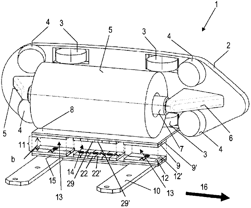
[0024] exist figure 1 shows schematically a shuttle 1 of a circular weaving machine with a housing 2 at which a plurality of support rollers 3 and a plurality of guide rollers 4 are arranged. Shuttle 2 moves along the running track 16 in the reed of circular loom, and reed is on figure 1 not shown in . Also for a better overview in the figures, all the threads and strings of the fabric produced on the circular loom are missing. At the inside of the shuttle 1 or inside its housing 2 there is a yarn reel or ribbon reel 5, which is loaded onto a cylindrical reel stand 7, preferably by means of a ball The bearing is fastened rotatably at the bracket 6 at the shuttle 1 . At the underside of the shuttle 1 or below the reel 5 , in the drive device according to the invention, suitably fastened a baffle 8 , at the underside of the baffle 8 correspondingly arranged next to each other with alternating Multiple individual magnets 9, 9' or 29, 29' of polarity.

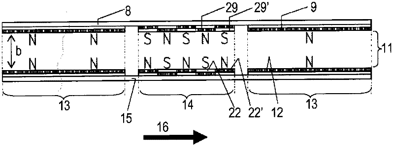
[0025] exist Figures...


PUM


Abstract

The invention relates to a device for driving a shuttle (1, 1') that can be moved in the reed (17) of a circular loom along a circular orbit (16) without contact, comprising at least one permanent magnet (29, 29') on the shuttle (1, 1') and at least one magnet (22, 22') that is operatively connected to the at least one permanent magnet (29, 29') of the shuttle (1, 1') and that is arranged on a drive element (10) that can be moved concentrically to the orbit (16) of the shuttle, wherein an air gap (11) is formed between the shuttle (1, 1') and the drive element (10). The at least one permanent magnet (29, 29') of the shuttle (1, 1') and the at least one magnet (22, 22') of the drive element (10) are polarized in such a way that the at least one permanent magnet of the shuttle and the at least one magnet of the drive element mutually attract each other by means of magnetic forces and thus form a magnetic attraction section (14).

Description

technical field [0001] The invention relates to a device for contactlessly driving a shuttle (Schuetze) movable along a running track (Umlaufbahn) in a reed (Riet) of a circular loom (Rundwebmaschine) with at least one A permanent magnet with at least one magnet in operative connection with at least one permanent magnet of the shuttle, the magnet is arranged on a drive element that can move concentrically to the running track of the shuttle, wherein a gap is formed between the shuttle and the drive element . Background technique [0002] In the prior art, for example the following devices are known for contactlessly driving the shuttles of circular looms: [0003] Document EP 0 167 831 A1 presents a weaving shuttle equipped with a permanent magnet on the rear side in its direction of movement, which is in operative connection with a permanent magnet of the same polarity fastened at the running drive element, And this is driven by magnetic repulsion. The advantage of this ...

Claims


Application Information

Patent Timeline
IPC IPC(8): D03D37/00D03D49/44D03D49/66
CPCD03D49/44D03D37/00D03D49/66
Inventor N·瓦格纳
Owner STARLINGER & CO GMBH
Why Eureka
Try Eureka