
Unhairing machine

A technology for a hair removal machine and a frame, which is applied in the field of hair removal machines, can solve the problems of easy corrosion of raw hides, pollution of the environment, easy production of industrial waste water, etc., and achieves the effect of avoiding damage

Inactive Publication Date: 2012-04-04
HUZHOU HUAFEI MACHINERY
View PDF10 Cites 7 Cited by
  • Summary
  • Abstract
  • Description
  • Claims
  • Application Information

AI Technical Summary

Problems solved by technology

[0002] Existing rawhide depilation technology adopts chemical method more, and for example Chinese Patent No. is the disclosed triethanolamine depilatory technique of the invention patent of 85102770, and Chinese Patent No. is the disclosed method of carrying out rawhide depilation with this enzyme of the invention patent of 95197015.1, and for example Chinese Patent No. 200810163968.0 discloses an ash-free, non-sulfurized alkali depilation and liming treatment method for buffalo leather tanning; however, chemical methods are used for depilation, which is easy to corrode raw hides, and is easy to produce industrial wastewater and pollute the environment

Method used


Image

  • Unhairing machine
  • Unhairing machine
  • Unhairing machine

Examples


Embodiment 1

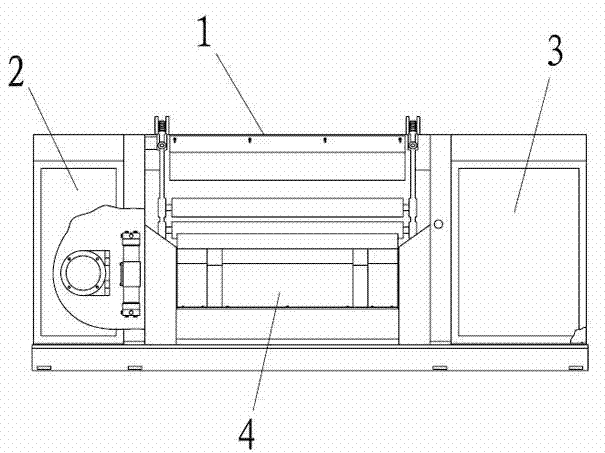
[0035] Embodiment 1: as figure 1 As shown, a hair removal machine includes a frame 1, a hydraulic system 2 located on one side of the frame 1, an electrical cabinet 3 located on the other side of the frame 1, and a transmission mechanism 4 located in the middle of the frame 1.

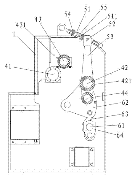
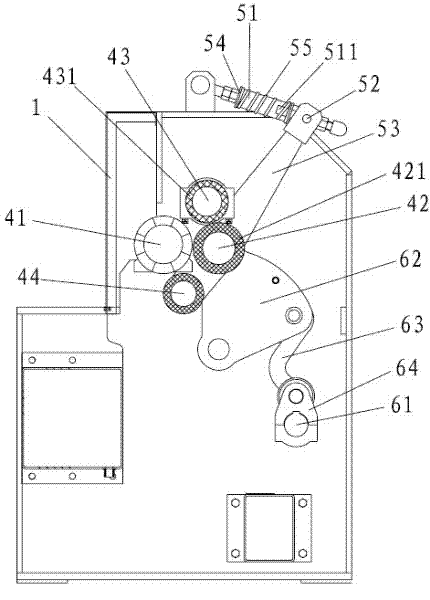
[0036] Such as Figures 2 to 3As shown, the transmission mechanism 4 includes an elastic compensation structure and a feed structure. The elastic compensation structure includes a slide bar 51 with one end hinged on the top of the frame 1 and having a chute 511, on the slide bar 51 and close to the slide bar 51 and the machine. A limit plate 54 is fixed at the hinge of the frame 1, a sliding column 52 is slidably connected in the chute 511, and a spring 55 that is always in a compressed state and is sleeved outside the slide bar 51 is arranged between the sliding column 52 and the limiting plate 54. The column 52 is hinged with one end of the connecting plate 53; the feed structure includes a synchron...

Embodiment 2

[0044] Embodiment 2: The difference from Embodiment 1 is that there are 6 left-handed threaded knife bands 412 and right-handed threaded knife bands 413 .

Embodiment 3

[0045] Embodiment 3: The difference from Embodiment 1 or 2 is that there are seven left-handed threaded knife bands 412 and right-handed threaded knife bands 413 .


PUM


Abstract

The invention relates to a peltry unhairing technology, and especially relates to an unhairing machine. The invention is realized through the following technical scheme: the unhairing machine comprises a frame, a hydraulic system arranged on one side of the frame, a regulator cubicle arranged on the other side of the frame and a transmission mechanism arranged in the middle of the frame. The transmission mechanism comprises a rotor hinged to the frame and a transport roller arranged in the frame; two ends of the transport roller are hinged to elastic compensation structures and feeding structures; the rotor comprises a rotating roller, and a left-hand screw thread-shape knife zone and a right-hand screw thread-shape knife zone, which are fixed on the rotating roller. The invention employs a physical mode to carry out unhairing on peltry, so as to avoid insufficient background technology and damage to the peltry.

Description

technical field [0001] The invention relates to raw hide hair removal technology, in particular to a hair removal machine. Background technique [0002] Existing rawhide depilation technology adopts chemical method more, and for example Chinese Patent No. is the disclosed triethanolamine depilatory technique of the invention patent of 85102770, and Chinese Patent No. is the disclosed method of carrying out rawhide depilation with this enzyme of the invention patent of 95197015.1, and for example Chinese Patent No. 200810163968.0 discloses an ash-free, non-sulfurized alkali depilation and liming treatment method for buffalo leather tanning; however, chemical methods are used for depilation, which is easy to corrode raw hides, and is easy to produce industrial wastewater and pollute the environment . Contents of the invention [0003] The object of the present invention is to provide a hair removal machine, which uses physical methods to remove hair from raw hides, avoids t...

Claims


Application Information

Patent Timeline
IPC IPC(8): C14B1/02C14B17/00C14B17/10
Inventor 凌伟杰
Owner HUZHOU HUAFEI MACHINERY
Learn More