Hollow floor system made of steel bar and foam combined filled member

A technology for filling components and hollow floors, which is applied in the direction of building components, floor slabs, building structures, etc., can solve the problems that the floors are easy to crack, easy to fall into the plastic foam filling components 1, and the surface strength is not large, etc. Insufficient binding force, labor cost saving, material cost saving effect

Active Publication Date: 2012-04-04
HUNAN BDF ENERGY SAVING TECH
View PDF12 Cites 98 Cited by
  • Summary
  • Abstract
  • Description
  • Claims
  • Application Information

AI Technical Summary

Problems solved by technology

[0003] However, because this kind of hollow floor uses a hollow thin-walled box made of pure inorganic cement cementitious material, the cement cementitious material used to make the thin-walled box takes a long time to solidify and harden, the utilization rate of molds and labor is low, and the hardened The density of the cement cement material is high, and the weight of the thin-walled box made of the cavity is heavy, which is inconvenient for production, transportation and on-site construction. Therefore, organic plastic foam is used to make hollow floor filling components on the market. figure 1 That is, the cross-sectional view of the hollow floor structure using plastic foam filling components in the prior art, such as figure 1 As shown, after the hollow floor formwork 2 is built, the base plate steel bars 3 are laid on the formwork 2, and the rib steel bars 4 are bound. A mesh-like space is formed between the rib steel ba

Method used


Image

  • Hollow floor system made of steel bar and foam combined filled member
  • Hollow floor system made of steel bar and foam combined filled member
  • Hollow floor system made of steel bar and foam combined filled member

Examples


Embodiment Construction

[0024] The invention will be further described below in conjunction with the accompanying drawings.

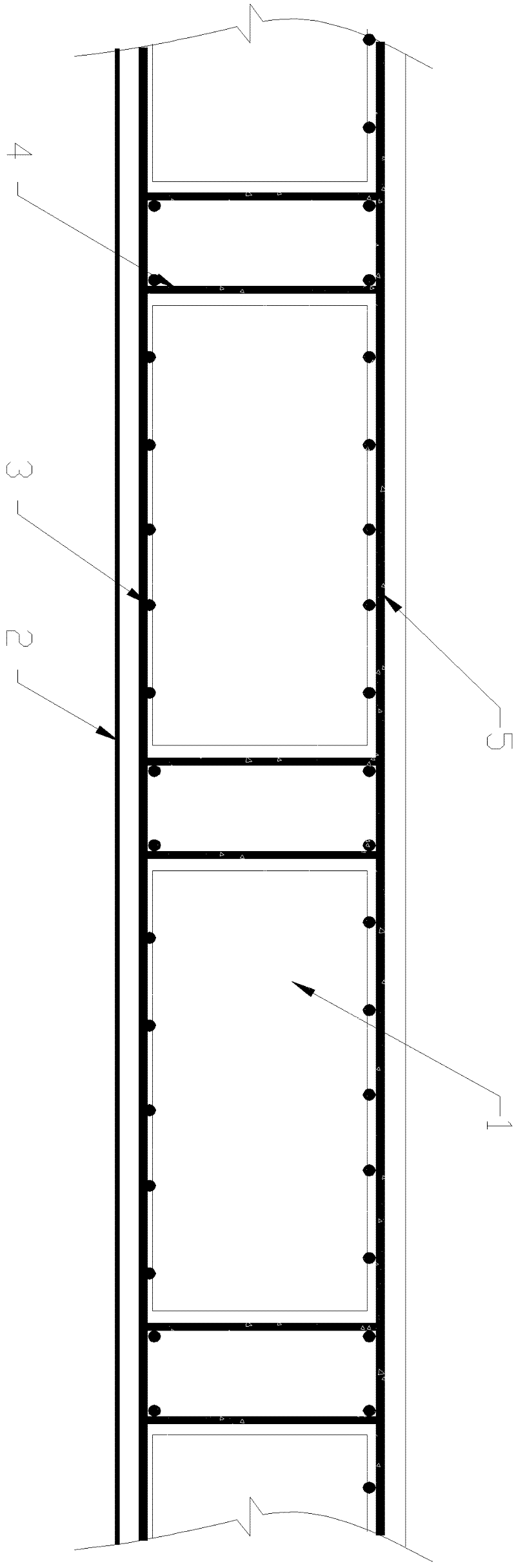
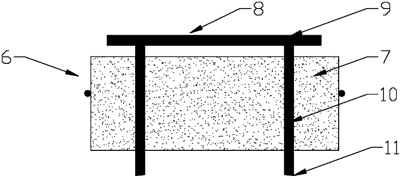
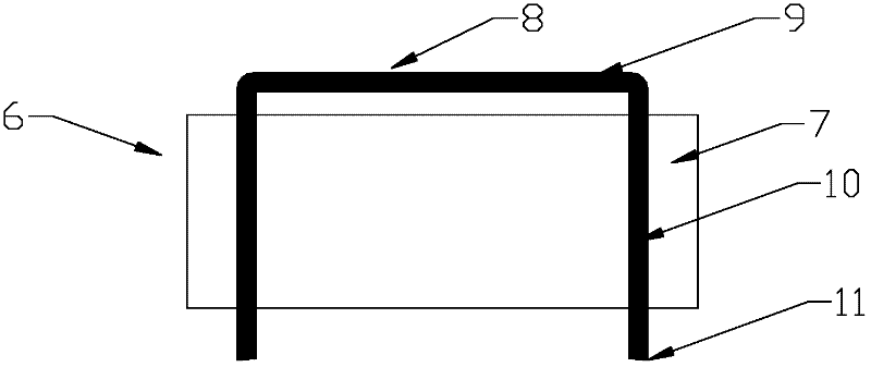
[0025] figure 2 It is a structural sectional view of the first embodiment of the reinforced foam composite filling member 6 used in the hollow floor of the present invention. like figure 2 As shown, the reinforced foam composite filling member 6 is composed of a plastic foam body 7 and a steel bar body 8, wherein the plastic foam body 7 is made of foamed plastic and is a solid plastic foam body. , the plastic foam body 7 can also be flame-retardantly treated by the usual flame-retardant technology, and the plastic foam body 7 can be made into different shapes and specifications according to the needs of architectural planning and design.

[0026] The reinforcing bar body 8 is made of isolated reinforcing bars 9 and supporting reinforcing bars 10, and the isolated reinforcing bars 9 and supporting reinforcing bars 10 are connected in an integral manner by welding the reinfo...


PUM


Abstract

The invention provides a hollow floor system made of a steel bar and foam combined filled member. The hollow floor system comprises an upper flange, a rib beam, a lower flange and the steel bar and foam combined filled member, wherein the steel bar and foam combined filled member consists of a plastic foam body and a steel bar body; the steel bar body comprises an isolation steel bar and support steel bars; the isolation steel bar and the support steel bars of the steel bar body are integrally manufactured or welded into a whole; the isolation steel bar is arranged on the upper surface of the plastic foam body; the support steel bars pass through the plastic foam body; the length of the support steel bars is greater than the height of the plastic foam body; and support points of the support steel bars are positioned on a template of the hollow floor system. A top plate steel bar and a bottom plate steel bar of the hollow floor system can be prevented from contacting or sinking into the plastic foam body, and the problem of insufficient bond stress of the steel bars and cast-in-situ concrete in the prior art is effectively solved; and cost can be saved, and the floor system is more conveniently and quickly constructed and has a more reasonable structure.

Description

technical field [0001] The invention relates to a novel building floor, in particular to a hollow floor made of reinforced foam composite filling components. Background technique [0002] At present, in the technical field of cast-in-place reinforced concrete cavity floors, cavity thin-walled box components are usually used to form cavity floors, such as ZL02282207.0 "Thin-walled box embodies thin-walled cavity panels for pouring cavity panels" declared by the inventor. According to the patent, the thin-walled box produced by inorganic cement cementitious material has thin hollow wall, light weight and high strength, and is widely used in cavity floor projects, such as the ZL200410082381.9 "one" declared by the inventor A kind of cavity small ribbed floor", the cavity thin-walled box forms a hollow layer in the small dense ribbed floor, which can save concrete for construction, reduce the height of the building, increase the sound insulation effect of the floor, and improve ...

Claims


Application Information

Patent Timeline
IPC IPC(8): E04B5/19E04B5/48
Inventor 王本淼王海崴
Owner HUNAN BDF ENERGY SAVING TECH
Why Eureka
Try Eureka