Apparatus for the production of pocketed coil springs

a technology apparatuses, which is applied in the field of apparatus and methods for the production of pocketed coil springs, can solve the problems of high production cost, slow response to special customer requirements, and long operation of resetting between one product and another, and achieves simple correction of variation in wire properties, facilitate creation and modification of tables, and facilitate the effect of changing

Inactive Publication Date: 2005-08-02
SPRINGFORM TECH
View PDF4 Cites 31 Cited by
  • Summary
  • Abstract
  • Description
  • Claims
  • Application Information

AI Technical Summary

Benefits of technology

[0022]Each table may consist of many data points, eg several thousand data points, resulting in complete control of the spring being formed. In order to facilitate the creation and modification of the tables, they can be created using a computer spreadsheet. This also enables viewing of a graphical representation of the movements of the axes relative to each other prior to the table being downloaded to the logic controller. The use of spreadsheets allows total flexibility in the desired spring profile, eg for development purposes. However, for established spring designs, it may simply be adequate to enter the desired pitch and diameter(s).
[0023]Any additional spring parameters, eg the number of convolutions or diameter modifications, may be entered directly via a control panel. This enhances changeovers and allows simple correction for variation in wire properties etc.

Problems solved by technology

Conventionally, synchronisation is achieved by a complex arrangement of gears and cams, making resetting between one product and another a lengthy operation needing high levels of training and experience.
Consequently, economic batch quantities are high and response to special customer requirements is slow.
Development of new spring designs is difficult, often relying on the creation of new cam profiles on a trial and error basis.
In addition, the maximum length of spring which can be produced is often severely limited.
Synchronisation of this section is also dependent on mechanical devices such as cams, linkages and a clutch all of which require resetting between products, with resulting loss of productivity and high maintenance costs.

Method used


Image

  • Apparatus for the production of pocketed coil springs
  • Apparatus for the production of pocketed coil springs
  • Apparatus for the production of pocketed coil springs

Examples


Embodiment Construction

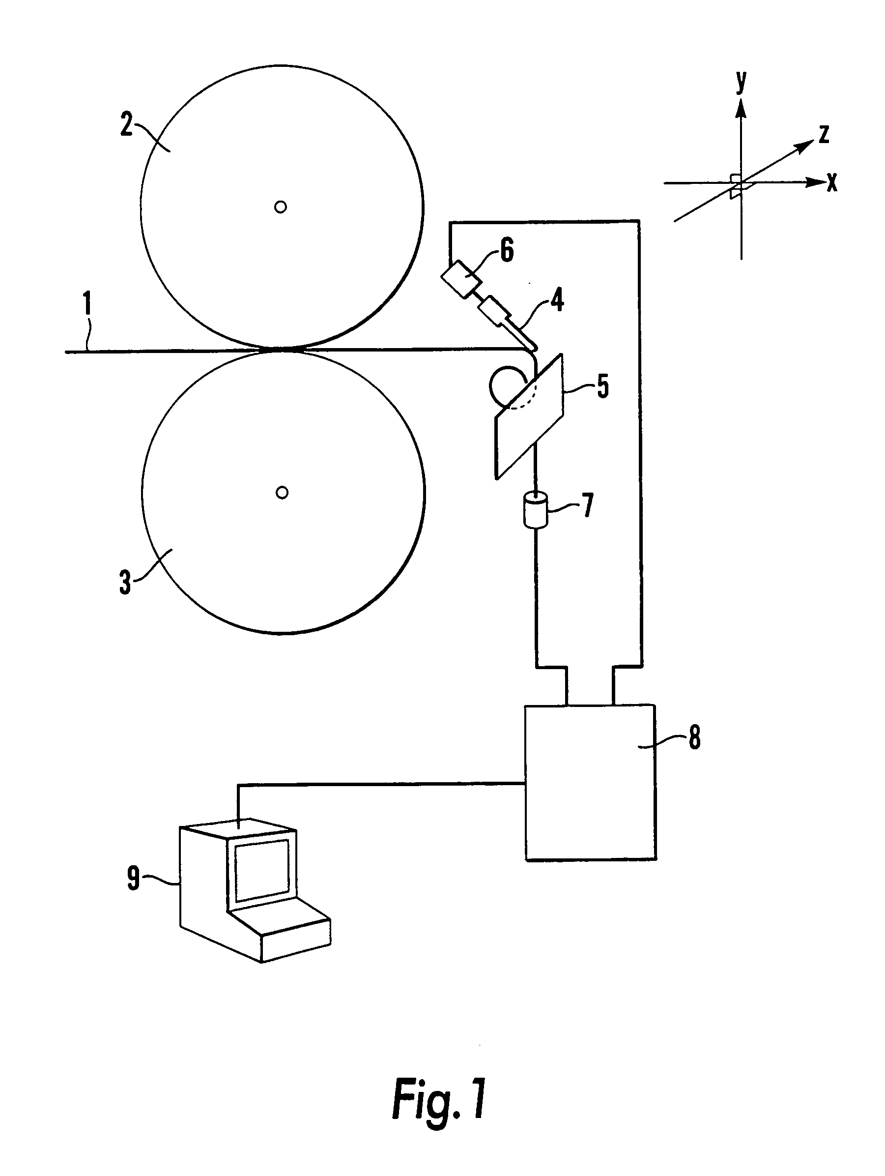
[0046]Referring first to FIG. 1, a coiling unit of an apparatus according to the invention is shown schematically and comprises three components which determine the form of the coil produced from wire 1 fed into the unit by conventional means. Those three components are a pair of feed rollers 2,3, a coiling finger 4 and a so-called spreader 5. The feed rollers 2,3 determine the axis along which the wire is fed to the finger 4 and spreader 5. This is the master axis in relation to which the orientational axes (slave axes) of the finger 4 and spreader 5 are adjusted. The orientation of the finger 4 and spreader 5 are governed by servo-motors 6,7 which are controlled by a programmable logic controller (PLC) 8. The PLC 8 is in turn linked to a computer control panel 9. Connection of the control panel 9 to the PLC 8 may be necessary only some of the time, eg for downloading of data to the PLC 8 or monitoring operation of the PLC 8. At other times, eg during normal operation, such connect...


PUM

PropertyMeasurementUnit
depthaaaaaaaaaa
depthsaaaaaaaaaa
depthsaaaaaaaaaa

Abstract

An apparatus for the production of pocketed coil springs is disclosed. The apparatus includes a coiling section in which a coil is formed from wire fed to the coiling section, the coiling section including coiling elements, whose position and/or orientation determines the form of the coil, and an encapsulation section in which the coil is inserted between juxtaposed sheets of material and in which the sheets of material are joined together to form a pocket enclosing the coil. The apparatus further includes programmable control means operably linked to the coiling elements in such a way as to control the position and/or orientation of the coiling elements.

Description

CROSS REFERENCE TO RELATED APPLICATIONS[0001]This application is a 35 U.S.C. §371 of PCT / GB99 / 00975, filed Mar. 29, 1999, and claims priority from U.K. Patent Application No. 9806778.8, filed Mar. 31, 1998, both of which are hereby incorporated by reference in their entirety.FIELD OF THE INVENTION[0002]This invention relates to apparatus and methods for the production of pocketed coil springs, and to pocketed spring assemblies.BACKGROUND OF THE INVENTION[0003]Pocketed coil springs, ie strings of springs enclosed within fabric pockets which are joined at their side seams, are widely used in the manufacture of mattresses, cushions and the like.[0004]Apparatus for the production of pocketed coil springs may generally be regarded as comprising two sections: a coiling unit in which the coil is formed and an encapsulation section in which the coil is inserted between two layers of material which are then joined together to form a pocket enclosing the spring.[0005]The coiling of the wire i...

Claims


Application Information

Patent Timeline
Patent Type & Authority Patents(United States)
IPC IPC(8): B21F33/04B21F33/00B68G9/00A47C27/06B21F3/02A47C23/04B21F27/16B21F35/00
CPCB21F33/04B68G9/00Y10T29/5197Y10T29/49613Y10T29/5187
Inventor WHITWORTH, IAN JAMES
Owner SPRINGFORM TECH
Why Eureka
Try Eureka