Nanoparticle, surface optical material and preparation method of surface optical material
A technology of nano-microspheres and surface optics, applied in the field of optical materials, to achieve the effects of high refractive index, strong binding ability, and simple synthesis
- Summary
- Abstract
- Description
- Claims
- Application Information
AI Technical Summary
Problems solved by technology
Method used
Image
Examples
Embodiment 1
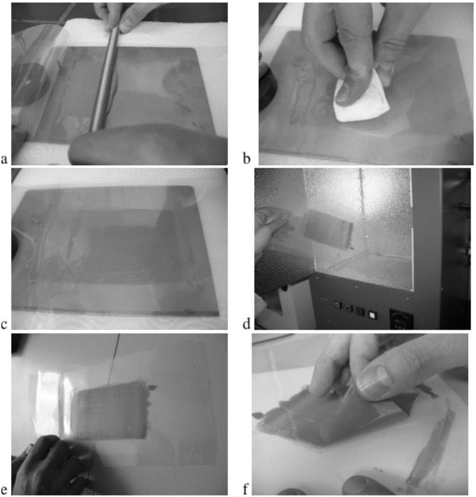
[0101] A surface optical material, the material comprises 320nm size core-shell structure nano microspheres, the preparation method comprises the following steps:
[0102] (1) Preparation of the nanospheres:
[0103] Core: use a 10-liter reactor with a stirrer, argon protection, heat to 75 degrees Celsius, pre-mix 2.6 grams of SDS, 2800 grams of deionized water, 36 grams of styrene monomer, 4 grams of DVB into the reactor, and the stirring speed of the reactor 250rpm, where DVB is used instead of BDDA as a crosslinking agent to make the polymerized polystyrene have a higher refractive index and improve the optical reflectance. Then add 0.72 g Na 2 S 2 o 5 and 5.18 g Na 2 S 2 o 8 . Twenty minutes later, 2.3 grams of SDS, 4 grams of NaOH, 2.2 grams of Dowfax2A1, 900 grams of deionized water, 700 grams of styrene monomer, and 70 grams of DVB were added at a rate of 10 ml per minute.
[0104] Transition layer: After 30 minutes, add a mixed solution of 0.25 grams of SPS and...
Embodiment 2
[0116] The finished optical thin film material prepared by the present invention generally has two layers of protective film up and down. When using it, one side of the protective film is peeled off as appropriate, and the exposed surface of the optical material is directly attached to the application target surface, such as Figure 5 shown.
[0117] Figure 5 The specific application method for the surface optical material is to peel off the protective film (P) on one side of the material (O), and then attach it to the cleaned surface substrate (S). This process depends on the surface roughness of the substrate. Adhesives may or may not be used.
Embodiment 3
[0119] The surface optical material prepared in embodiment 1 can be applied in the following manner:
[0120] 3.1 as Figure 6 packaging materials shown. Figure 6 For the application of the surface optical material as a product packaging material, take a pharmaceutical packaging box as an example. After removing the protective film on one side of the material, the exposed surface of the optical material (O) can be directly pressed or pasted on the surface of the product packaging box (B) due to its high viscosity, such as paper or plastic packaging on (OB).
[0121] 3.2 as Figure 7 and 8 Electromagnetic induction shown. Figure 7 It is an example of the application of electrochromic composite optical film with water as the flexible electrode material. The film (O) is attached to a layer of VHB polymer substrate (V), and there are flexible electrodes (W) made of deionized water on the upper and lower sides. After the light emitted by the lower light source passes throu...
PUM
| Property | Measurement | Unit |
|---|---|---|
| size | aaaaa | aaaaa |
| wavelength | aaaaa | aaaaa |
Abstract
Description
Claims
Application Information
 - R&D
- Intellectual Property
- Life Sciences
- Materials
- Tech Scout
- Unparalleled Data Quality
- Higher Quality Content
- 60% Fewer Hallucinations
Browse by: Latest US Patents, China's latest patents, Technical Efficacy Thesaurus, Application Domain, Technology Topic, Popular Technical Reports.
© 2025 PatSnap. All rights reserved.Legal|Privacy policy|Modern Slavery Act Transparency Statement|Sitemap|About US| Contact US: help@patsnap.com


