
Spring return type high-box locking mechanism

A spring return and locking mechanism technology, applied in the aviation field, can solve the problems of flight attendant or passenger injury, reduce friction, wear and other problems, and achieve the effect of convenient operation, high reliability and durability

Active Publication Date: 2012-04-04
JIANGSU UNBEATABLE RADIATOR
View PDF4 Cites 4 Cited by
  • Summary
  • Abstract
  • Description
  • Claims
  • Application Information

AI Technical Summary

Problems solved by technology

[0003] Long-term repeated rotation of the baffle around the shaft will cause the two to wear each other, and long-term wear will reduce the friction between the two, thereby reducing the stability of the baffle
During the take-off process of the aircraft, there will be relatively severe high-frequency vibrations. Under this vibration, the baffle will rotate around the axis of rotation to the horizontal direction under the action of its own gravity, and the whole fuselage of the aircraft has a large inclination angle during the take-off process. , once the baffle itself rotates to the horizontal direction, its blocking effect disappears, and the high box will slide out of the combination cabinet under its gravity and hit the ground of the engine room. Such an accident will cause damage to the engine room and the high box on the one hand. On the other hand, if the high box hits the flight attendant or passenger, it will cause more serious injuries.

Method used


Image

  • Spring return type high-box locking mechanism
  • Spring return type high-box locking mechanism
  • Spring return type high-box locking mechanism

Examples


Embodiment Construction

[0016] The present invention will be further described below in conjunction with the accompanying drawings and embodiments.

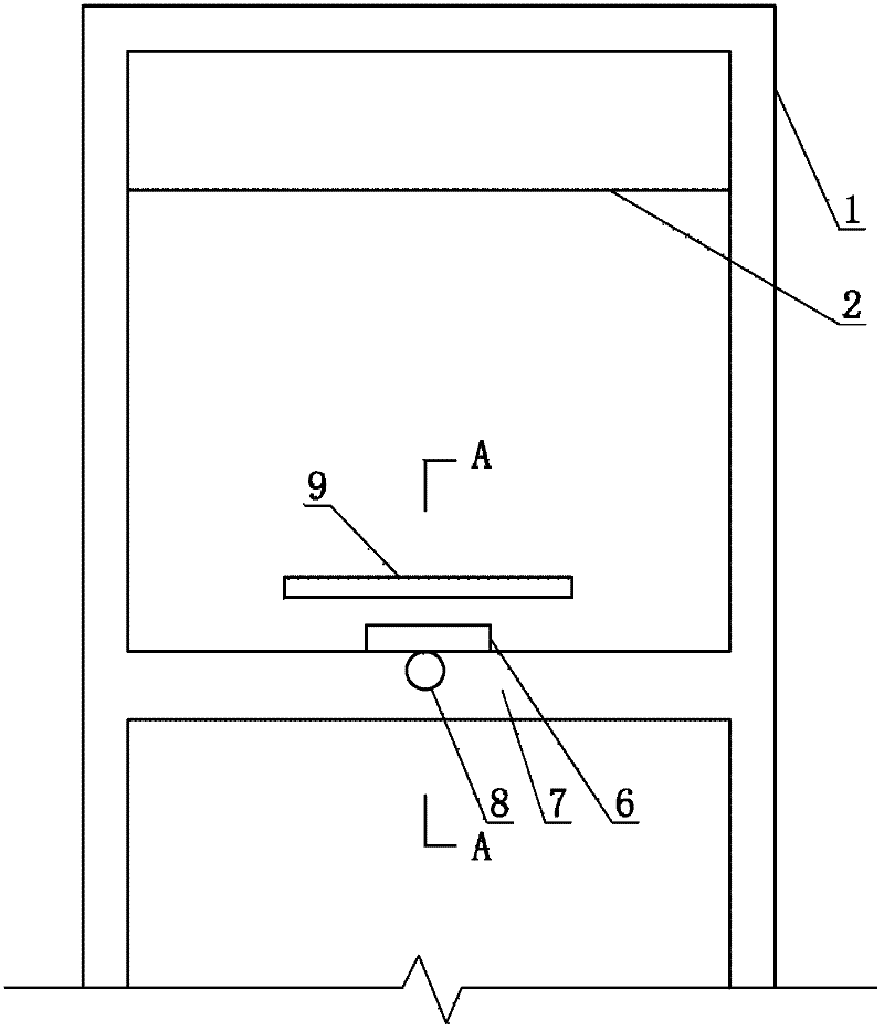
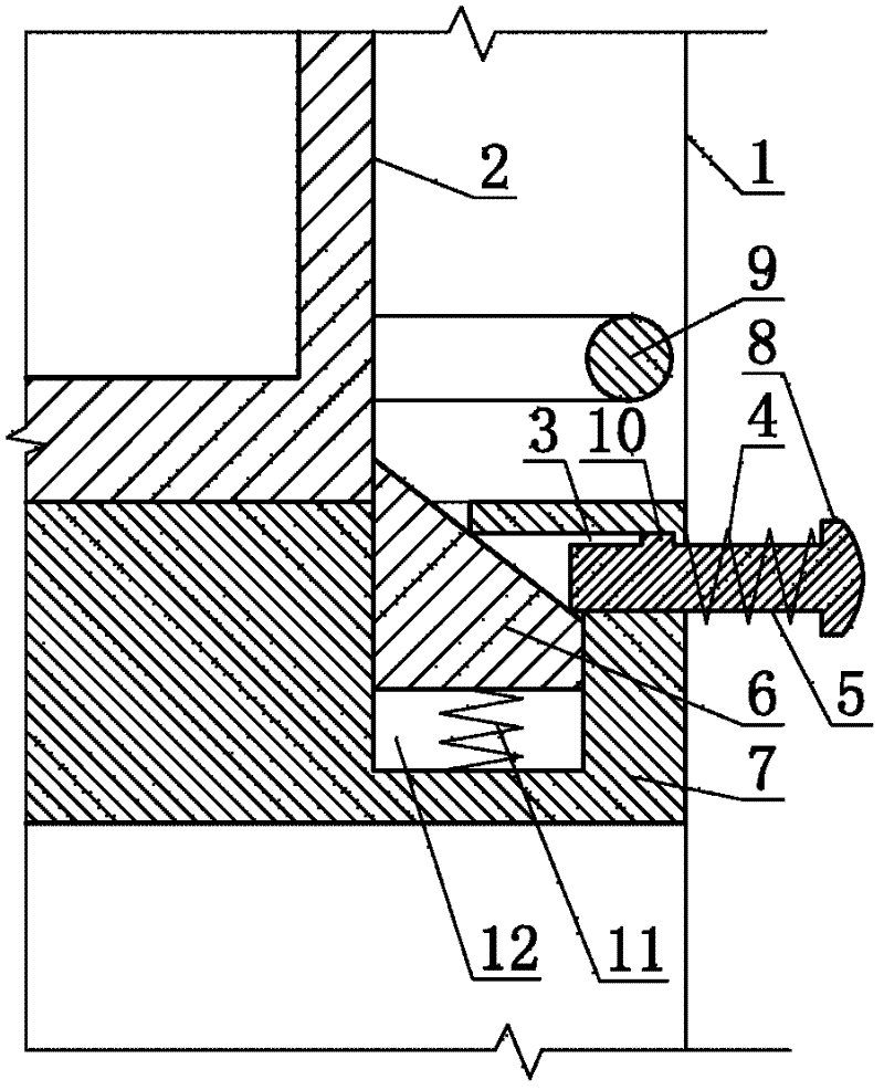
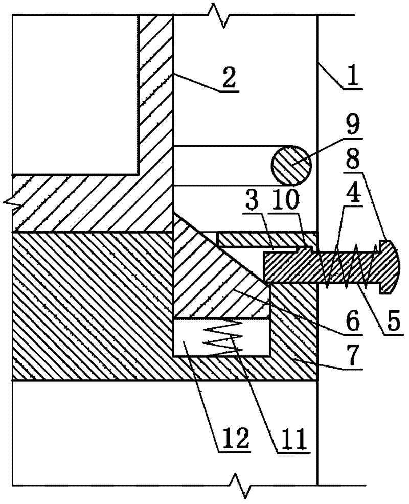
[0017] The spring return type high box locking mechanism consists of a cabinet body 1, a high box 2, a socket 3, a return spring 4, a button rod 5, a lock block 6, a drawer bottom plate 7, a button head 8, a handle 9, a protrusion 10, and a locking spring 11 And lock block cavity 12 constitutes. Wherein, the cabinet body 1 and the drawer bottom plate 7 horizontally fixed in the cabinet body 1 constitute a drawer cavity, and the high box 2 is located in the drawer cavity and forms a dynamic cooperation relationship with the drawer cavity. The outer end bottom of high case 2 has the handle 9 that is an integral body with high case 2. There is a distance between the upper surface of the high box 2 and the top surface in the drawer cavity, which is 1 / 5-1 / 4 of the height of the high box 2. The lock block cavity 12 is a vertical blind hole with a rectangula...


PUM


Abstract

The invention relates to the technical field of aviation, in particular to a spring return type high-box locking mechanism. The spring return type high-box locking mechanism consists of a cabinet body, a high box, a jack, a return spring, a button rod, a locking block, a drawer bottom plate, a button head, a handle, a boss, a locking spring and a locking block cavity, wherein the cabinet body andthe drawer bottom plate form a drawer cavity, and the high box is positioned in the drawer cavity. The locking block cavity is a blind hole positioned in the vertical direction in the drawer bottom plate, the jack is a blind hole positioned in the horizontal direction in the drawer bottom plate, and the locking block cavity is communicated with the jack. The locking block is positioned in the locking block cavity, one end of the button rod is inserted into the jack, and the other end of the button rod is the button head integrated with the button rod; and the return spring is sheathed on the button rod. In the spring return type high-box locking mechanism, the locking state of the high box is not eliminated due to high-frequency vibration of a plane body, and the reliability and the durability are higher.

Description

technical field [0001] The invention relates to the field of aviation technology, in particular to a spring return type high box locking mechanism. Background technique [0002] The side of the emergency escape passage of the existing civil aviation airliner is provided with a metal combination cabinet integrating a dining car, a locker and a filing cabinet. High boxes for storing infrequently used items are arranged on the top of the combination cabinet. In order to facilitate removal, the combination of these high boxes and combination cabinets adopts a drawer structure. In order to fix the high box, a block with a rotating shaft at one end is arranged on the outer edge of the combination cabinet. The shaft is fixed to the combination cabinet, and the block Can rotate around the axis. Normally, the baffle is rotated to the vertical direction to prevent the high box from sliding; when the high box needs to be taken, the baffle is rotated to the horizontal state. But the ...

Claims


Application Information

Patent Timeline
IPC IPC(8): E05B65/52
Inventor 梁伟
Owner JIANGSU UNBEATABLE RADIATOR
Learn More