
Cylinder-deactivation tappet device of engine

An engine and relative motion technology, applied in the direction of engine components, engine control, machine/engine, etc., can solve the problems of difficult engine cylinder technology and small installation space, and achieve high practical value, reduce fuel consumption, and reduce emissions.

Inactive Publication Date: 2012-04-04
SAIC MOTOR
View PDF6 Cites 6 Cited by
  • Summary
  • Abstract
  • Description
  • Claims
  • Application Information

AI Technical Summary

Problems solved by technology

However, for the cam directly driven tappet type valve mechanism, due to its few parts and small installation space, it is technically difficult to realize the engine tappet

Method used


Image

  • Cylinder-deactivation tappet device of engine
  • Cylinder-deactivation tappet device of engine
  • Cylinder-deactivation tappet device of engine

Examples


Embodiment Construction

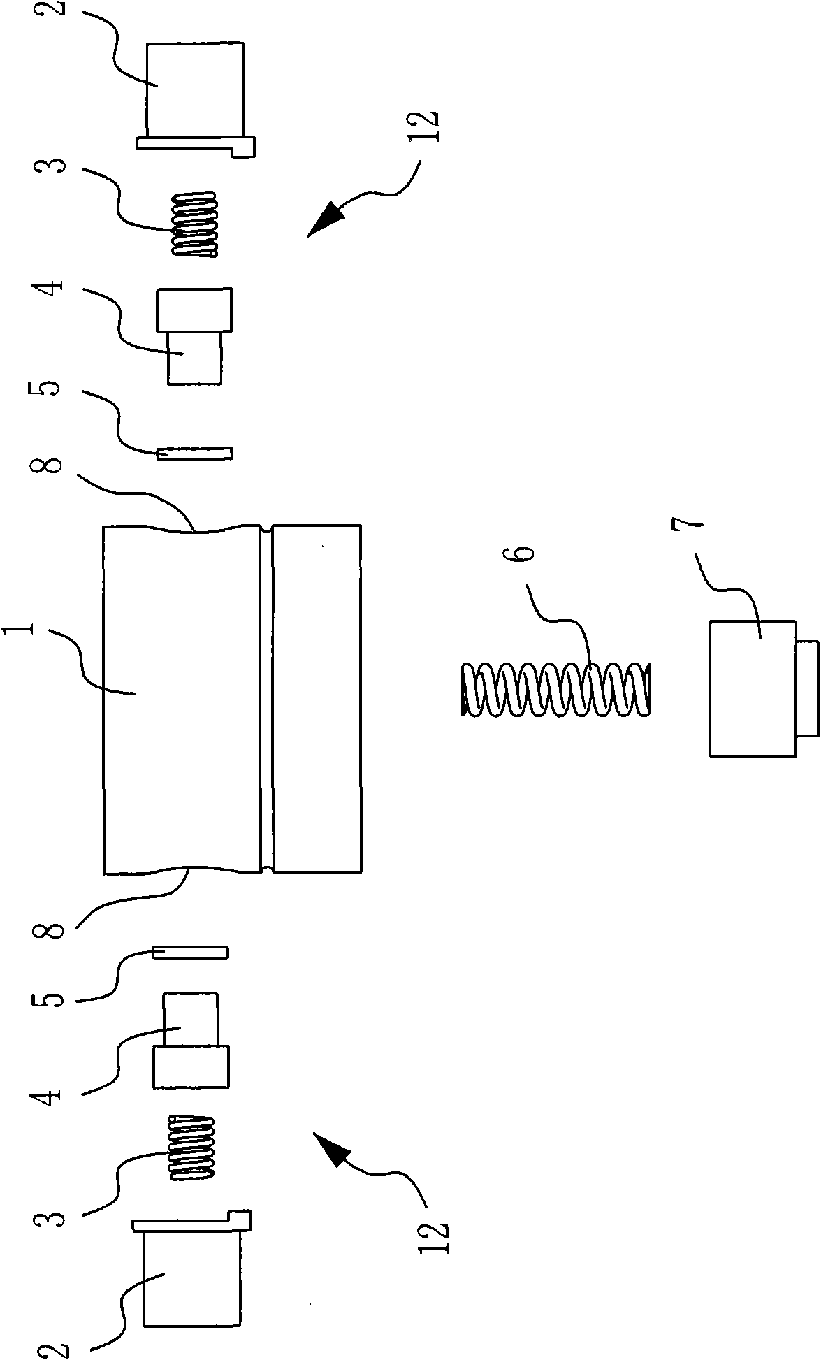
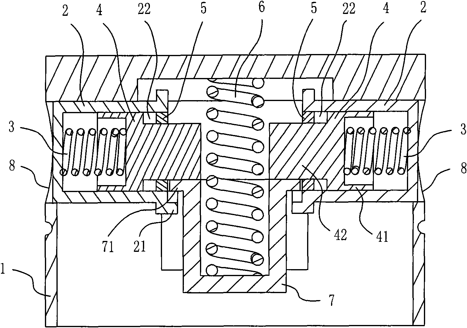
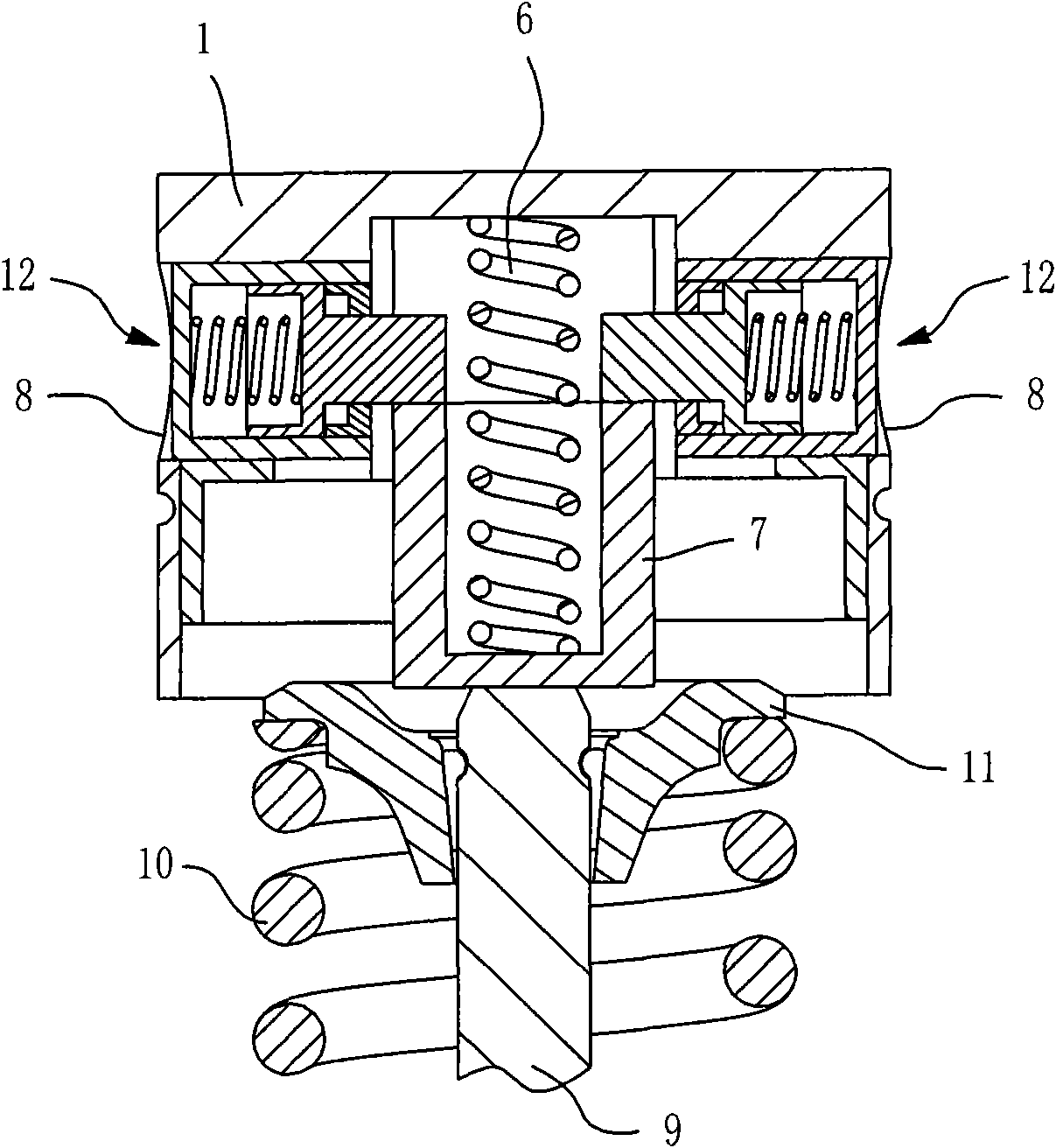
[0043] Please also see figure 1 and figure 2 , which schematically show the overall structure of a preferred embodiment of the engine deactivation tappet device of the present invention. In this preferred embodiment, the engine cylinder deactivation tappet device mainly includes a housing 1, a bracket 7 and a lock pin assembly 12, and these components will be described in detail below.

[0044] Such as figure 2 As shown, the housing 1 is covered on the valve mechanism, and the upper end of the housing 1 is a closed structure and is in contact with the cam on the camshaft of the valve drive group, and at the same time, the side wall of the housing 1 is also radially Two openings 8 are arranged symmetrically. In some other unshown embodiments, the above-mentioned openings can also be flexibly set according to actual needs, for example, three, four or more openings can be symmetrically set along the circumferential direction of the housing 1 .

[0045] The bracket 7 is inst...


PUM


Abstract

The invention relates to a cylinder-deactivation tappet device of an engine. The cylinder-deactivation tappet device comprises a shell, a bracket and lock pin components, wherein the shell covers a valve mechanism, the upper end of the shell is closed, and the shell is contacted with a cam; at least two openings are arranged on the side wall of the shell; the bracket is arranged inside the shell, and one end of the bracket is pressed against a valve rod of the valve mechanism by using a first elastic part which is clamped between the bracket and the shell; and the lock pin components are arranged in each opening and constructed to be in contact fit with the bracket during normal operation of the engine to keep the shell and the bracket from relatively moving, and during cylinder deactivation of the engine, the lock pin components are separated from the bracket to make the shell capable of moving relative to the bracket under the action of the cam. By adoption of the cylinder-deactivation tappet device of the engine, long-lift and zero-lift two-stage adjustment of valve lift can be realized, so that valve movement can be stopped when necessary so as to cause cylinder deactivation of the engine to reduce oil consumption and discharge of harmful gas; and an original tappet can be directly replaced with the cylinder-deactivation tappet device without replacement of a cylinder cover of the engine. Therefore, the cylinder-deactivation tappet device is good in technical expansibility and high in practical value.

Description

【Technical field】 [0001] The invention relates to a tappet device, in particular to an engine deactivation tappet device capable of realizing two-stage adjustable lift of a valve mechanism in long lift and zero lift. The invention belongs to the technical field of automobiles. 【Background technique】 [0002] In order to ensure that the car has sufficient power when accelerating or climbing a slope, it is necessary to reserve reserve power for the engine during design. This will cause the engine to often work under low-load conditions, thereby causing problems such as low efficiency and high fuel consumption. In this regard, engine cylinder deactivation technology can be used to solve it. "Engine cylinder deactivation" refers to stopping the work of certain cylinders in the engine cylinders under specific working conditions, and at the same time stopping the movement of the valves. Therefore, in order to ensure that the total output power of the engine remains unchanged, the...

Claims


Application Information

Patent Timeline
Patent Type & Authority Applications(China)
IPC IPC(8): F01L13/00F02D13/06
Inventor 武涛李冲霄钱承炬张华郝晓伟孔毅
Owner SAIC MOTOR
Learn More