Detent escapement for timepiece and mechanical timepiece

A technology of escapement mechanism and pawl, which is applied in the direction of escapement mechanism, mechanically driven clocks, clocks and watches, etc. It can solve the problems of cumbersome position adjustment operations, and achieve the effect of suppressing the increase of manufacturing cost and reliable operation

Inactive Publication Date: 2012-04-04
SEIKO INSTR INC
View PDF8 Cites 8 Cited by
  • Summary
  • Abstract
  • Description
  • Claims
  • Application Information

AI Technical Summary

Problems solved by technology

Therefore, the position adjustment work of the pawl lever 30...

Method used


Image

  • Detent escapement for timepiece and mechanical timepiece
  • Detent escapement for timepiece and mechanical timepiece
  • Detent escapement for timepiece and mechanical timepiece

Examples


no. 1 approach

[0074] (mechanical clock)

[0075] Below, according to Figure 1 to Figure 8 A first embodiment of the present invention will be described.

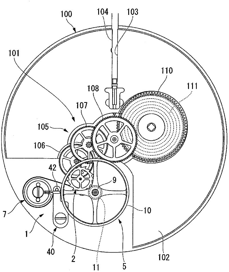
[0076] figure 1 It is a plan view of the movement of the mechanical timepiece viewed from the back cover side.

[0077] As shown in the figure, the mechanical timepiece 100 includes a movement 101 . The movement 101 has a main plate 102 constituting a substrate of the movement 101 . An arbor guide hole 103 is formed in the main plate 102 , and an arbor 104 is rotatably assembled in the arbor guide hole 103 .

[0078] In addition, on the back side of the movement 101 ( figure 1The inner side of the paper in the middle) is equipped with a switching device (not shown) comprising a pull gear, a clutch lever and a clutch lever press bar. Through this switching device, the axial position of the stem 104 is determined.

[0079] On the other hand, on the surface side of the movement 101 ( figure 1 The front side of the paper in the fi...

no. 2 approach

[0165] Below, according to Figure 9 A second embodiment of the present invention will be described. In addition, the same code|symbol is attached|subjected to the same point as 1st Embodiment, and description is abbreviate|omitted (it is the same also about the following embodiment).

[0166] Figure 9 It is a main part plan view of the pawl in 2nd Embodiment.

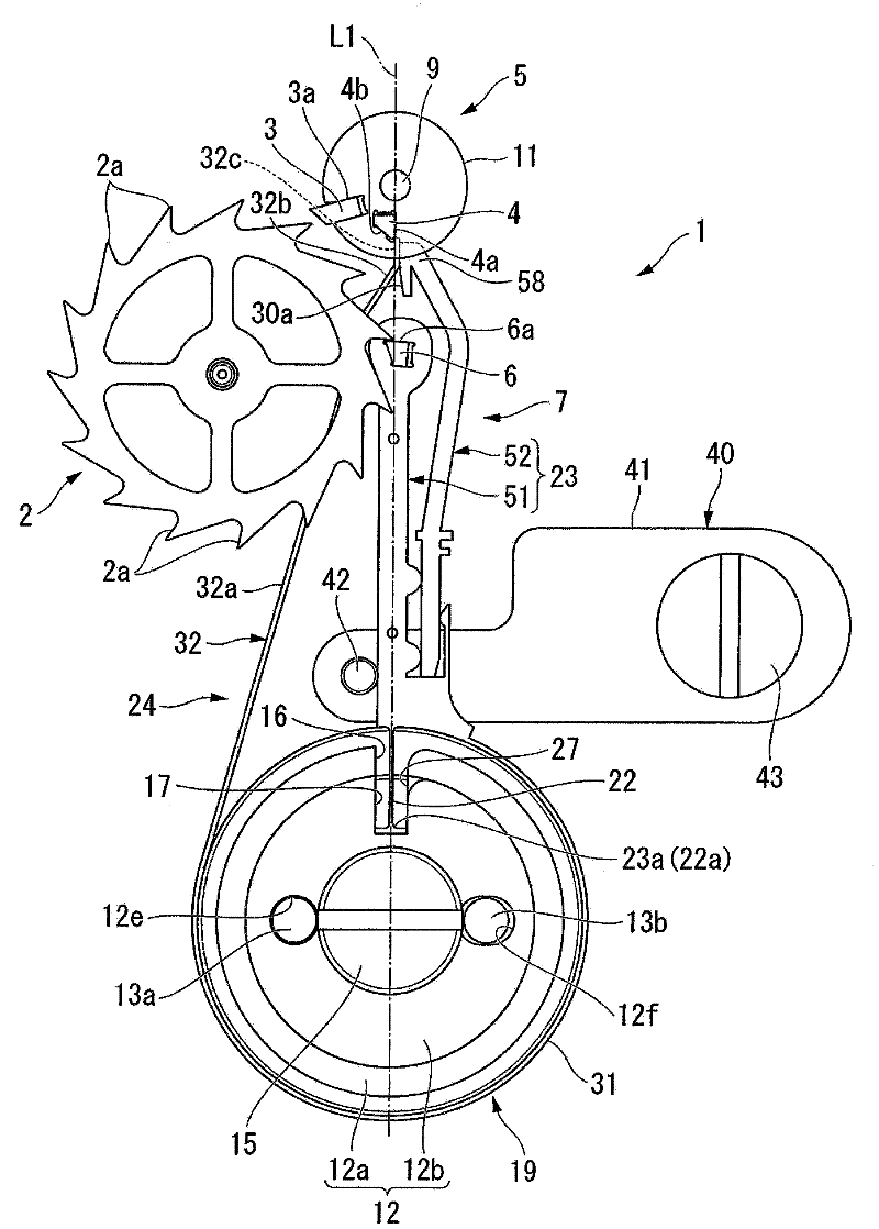
[0167] In this second embodiment, the basic structure is the same as that of the above-mentioned first embodiment (the same applies to the following embodiments) in that the mechanical timepiece 100 includes a movement 101; The surface side is provided with a pawl escapement mechanism 1 that controls the rotation of the surface side wheel train 105; the pawl escapement mechanism 1 includes: an escape wheel 2 that is rotated by rotation of the fourth wheel 106; 72, which has a stop drill 6 capable of coming into contact with the toothing 2a of the escape wheel 2; 2a, the release drill 4 can contact the pawl 72; the...

no. 3 approach

[0173] Below, according to Figure 10 A third embodiment of the present invention will be described.

[0174] Figure 10 is a plan view of main parts of the pawl in the third embodiment.

[0175]As shown in the drawing, this third embodiment differs from the first embodiment in the following points. That is, in the ratchet 73 of the third embodiment, a plurality of grooves 82 capable of engaging with the hook portion 63 of the engaging piece 62 are formed in the attachment portion 356 of the lever adjustment portion 52 . In addition, the lever adjustment part 52 can be moved to slide relative to the lever main body 51 in stages corresponding to the plurality of grooves 82 .

[0176] In this manner, the groove 82 and the hook 63 function as a positioning mechanism for the rod adjustment unit 52 . Therefore, according to the third embodiment described above, the same effects as those of the second embodiment described above can be achieved.


PUM


Abstract

An object of the invention is to provide a detent escapement for a timepice and a mechanical timepiece capable of easily performing the position adjustment operation of parts and operating reliably normally an escape wheel. The detent escapement for the timepiece comprises: an escape wheel (2); a balance (5) that includes an impulse jewel (3) which can contact a wheel tooth (2a) of the escape wheel and an unlocking stone (4), and that freely oscillates about a balance staff (9); a blade (23) that includes a locking stone (6) which can contact the wheel tooth (2a) of the escape wheel, and thatis supported being capable of approaching to and separating from the escape wheel; and a one-side actuating spring (24) that can contact the unlocking stone (4) and be elastically deformed along the approaching and separating direction with respect to the blade (23), wherein the blade (23) is constituted of a blade main body (51) and a blade adjustment portion (52) that is separated from the blade main body (51).

Description

technical field [0001] The present invention relates to a pawl escapement mechanism for a timepiece and a mechanical timepiece using the pawl escapement mechanism for a timepiece. Background technique [0002] Conventionally, a detent escapement (Detent Escapement) is known as an escapement mechanism for maintaining the rate (step) of a mechanical timepiece. The mechanism of this escapement is roughly divided into these two types of spring detent escapement (Spring Detent Escapement) and pivotal detent escapement (pivoted detent escapement) (for example, see Patent Document 1, Patent Document 2 and non-patent literature 1). [0003] Next, the basic structure of each pawl escapement mechanism will be described. [0004] Figure 16 It is a perspective view showing an example of a conventional spring type detent escapement. [0005] As shown in the figure, the spring type detent escapement 300 includes: an escape wheel 301 ; a balance with hairspring 303 freely vibrating abo...

Claims


Application Information

Patent Timeline
IPC IPC(8): G04B15/14G04B15/00
CPCG04B15/06
Inventor 内山博纪岸松雄新轮隆幸田雅行佐藤未英
Owner SEIKO INSTR INC
Why Eureka
Try Eureka