Combine harvester

A technology of combine harvester and body, applied in the direction of harvester, cutter, chassis of agricultural machinery, etc., can solve problems such as increase in manufacturing cost, and achieve the effect of suppressing increase in manufacturing cost and facilitating fuel supply

Inactive Publication Date: 2018-09-07
KUBOTA LTD
View PDF8 Cites 0 Cited by
  • Summary
  • Abstract
  • Description
  • Claims
  • Application Information

AI Technical Summary

Problems solved by technology

As a result, manufacturing costs increase

Method used


Image

  • Combine harvester
  • Combine harvester
  • Combine harvester

Examples


Embodiment Construction

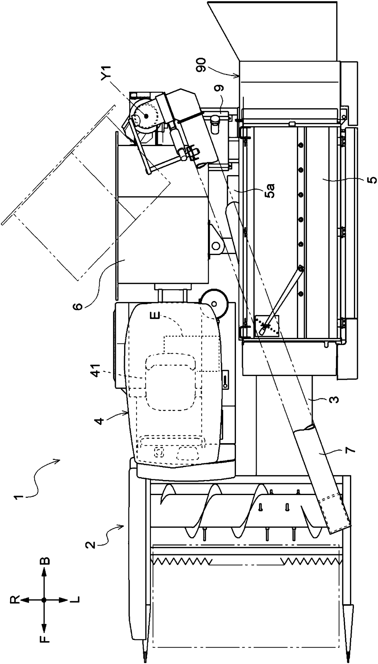
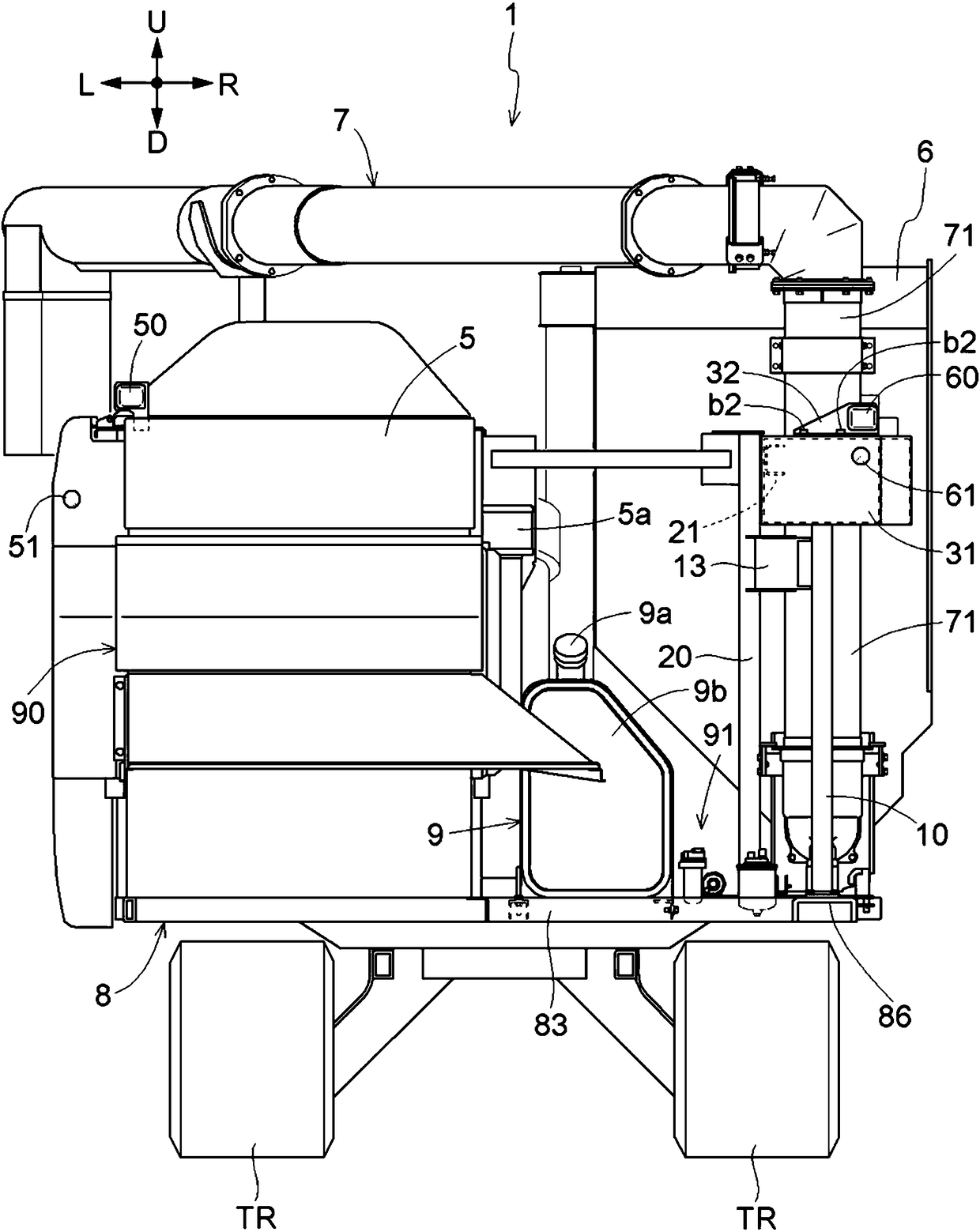
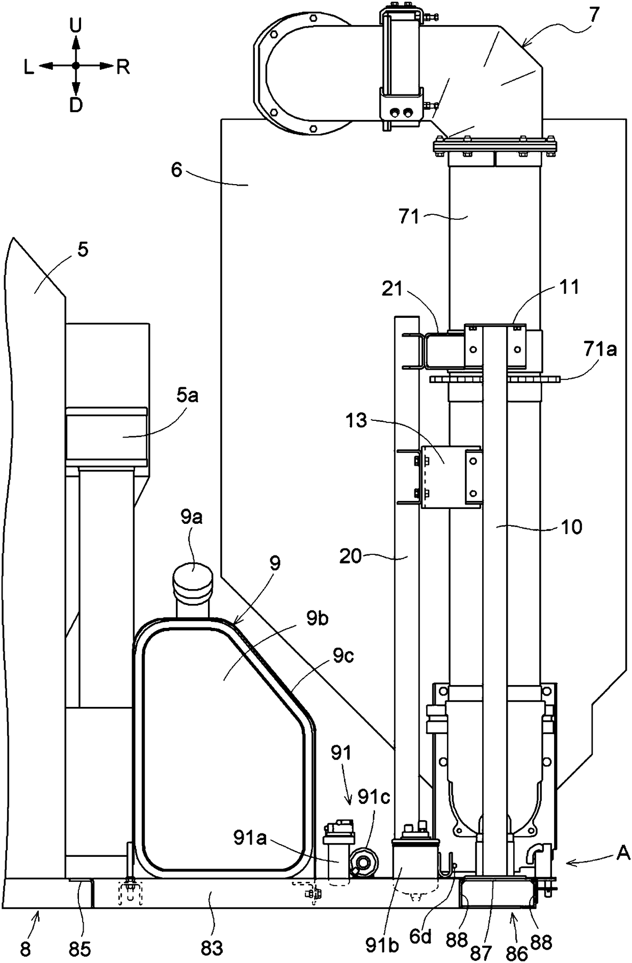
[0080] Embodiments for implementing the present invention will be described based on the drawings. Also, in the following description, the figure 1 , Figure 4 to Figure 6 , Figure 8 , Figure 10 to Figure 12 The direction of the arrow F shown is "front", the direction of the arrow B is "rear", and the Figure 1 to Figure 4 , Figure 6 to Figure 8 , Figure 11 The direction of the indicated arrow L is referred to as "left", and the direction of arrow R is referred to as "right". Additionally, the figure 2 , image 3 , Figure 5 , Figure 7 , Figure 9 , Figure 10 , Figure 12 The direction of arrow U shown is "up", and the direction of arrow D is "down".

[0081] 〔The overall structure of the combine harvester

[0082] Such as figure 1 and figure 2 As shown, the full-feed combine harvester 1 has: a harvesting part 2, a feeding device 3, a driving part 4, a threshing device 5, a grain tank 6, a grain discharge device 7, and an engine E.

[0083] The harves...


PUM


Abstract

The present invention provides a combine harvester that facilitates fuel supply to a fuel tank and can suppress an increase in manufacturing cost. The combine has a threshing device (5) and a grain tank (6) disposed in a state of being horizontally aligned with the threshing device (5), and a fuel tank (9) is disposed at a rear end portion of the body, and the fuel tank (9) is provided The first cross frame (83) is disposed and supported at a rear end of the body and extending in the left-right direction.

Description

technical field [0001] The invention relates to a combine harvester having a fuel tank. Background technique [0002] As the above-mentioned combine, for example, the combine described in patent document 1 is known. This combine has a cab and a grain collecting section, and the grain collecting section is arranged behind the cab. And in this combine, a fuel tank is arrange|positioned at the position between a driving part and a grain recovery part in the front-back direction. [0003] prior art literature [0004] patent documents [0005] Patent Document 1: Japanese Patent Laid-Open No. 2007-151440 [0006] The problem to be solved by the invention [0007] In the above-mentioned combine, the fuel tank is disposed at a position higher than the driver's seat. Therefore, when refueling the fuel tank, the operator needs to climb onto the machine body and lift the refill container to a relatively high position. [0008] Here, in the said combine, it is conceivable to arr...

Claims


Application Information

Patent Timeline
IPC IPC(8): A01D41/02A01D67/04A01D69/03
CPCA01D41/02A01D67/04A01D69/03
Inventor 山本裕明丸山纯一村山贤多甲斐裕一上北千春猿渡贤治堀内真幸
Owner KUBOTA LTD
Why Eureka
Try Eureka