
Double-disc-type symmetric exhaust electrostatic spraying chamber

An electrostatic spraying, double-disc technology, applied in the direction of electrostatic spraying devices, spray booths, liquid spraying equipment, etc., can solve problems such as complex operation, adverse effects on yield, uneven paint on the working surface, etc., to reduce exhaust air Quantity, increase yield, convenient refueling effect

Inactive Publication Date: 2017-03-22
赛智环保科技(天津)有限公司
View PDF7 Cites 0 Cited by
  • Summary
  • Abstract
  • Description
  • Claims
  • Application Information

AI Technical Summary

Problems solved by technology

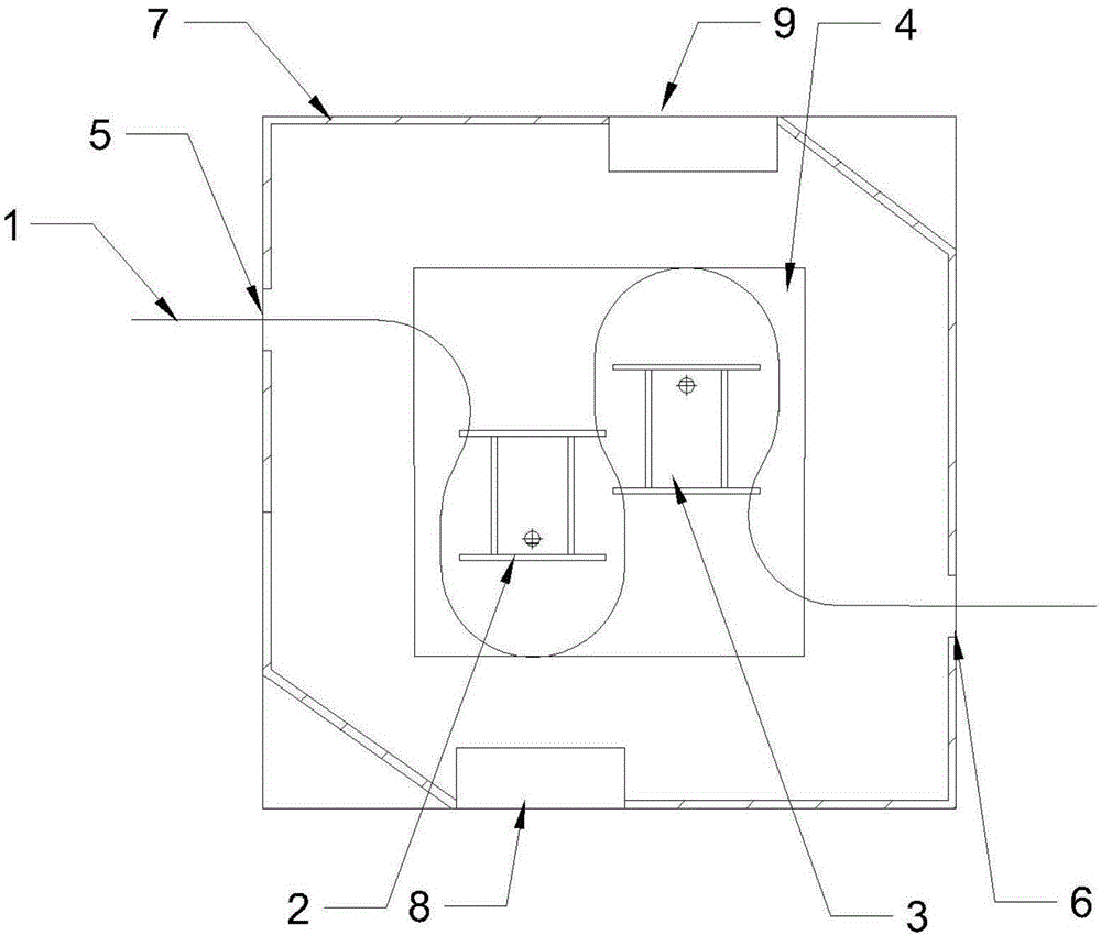
[0002] Only one single-disc spraying device is installed in the traditional electrostatic spraying room. The working principle of the single-disc spraying device is that the workpiece is suspended on the conveying chain, and the conveying chain surrounds the spray gun in an Ω shape, and the conveying chain drives the workpiece through the spray gun. , to achieve all-round spraying and coating. When the workpiece moves to the arc-shaped apex of the Ω-shaped track around the spray gun, the workpiece rotates half a circle under the action of the reversing mechanism to complete the double-sided spraying. In this process, due to factors such as chain speed, often It causes unbalanced painting on the working surface, which has a negative impact on the yield, and at the same time increases the workload of repairing personnel in the later stage, and the operation is complicated when changing the paint material, which is not suitable for a small amount of flexible painting process
The traditional spraying room adopts a single fan exhaust, which will make the air distribution in the double-disc spraying room chaotic and affect the spraying effect

Method used


Image

  • Double-disc-type symmetric exhaust electrostatic spraying chamber

Examples


Embodiment Construction

[0012] Below in conjunction with accompanying drawing and specific embodiment the present invention is described in further detail:

[0013] As shown in the figure, a double-disc type symmetrical exhaust electrostatic spraying room includes a conveying track 1, a first spraying gun 2, a second spraying gun 3, a spraying area 4, a workpiece inlet 5, a workpiece outlet 6, and a water curtain Plate 7, the first exhaust port 8 and the second exhaust port 9, the square area in the center of the spraying room is the spraying area, and the first spraying gun and the second spraying gun are arranged in a staggered manner in the spraying area. The workpiece inlet is set on the inner wall of the spraying room corresponding to the gun, and the workpiece outlet is set on the inner wall of the other side of the spraying room corresponding to the second spraying gun. The gun reaches the workpiece exit once to form an S-shaped track, and the first exhaust port and the second exhaust port are...


PUM


Abstract

The invention discloses a double-disc-type symmetric exhaust electrostatic spraying chamber. The double-disc-type symmetric exhaust electrostatic spraying chamber comprises a conveying rail, a first spraying gun, a second spraying gun, a spraying area, a workpiece inlet, a workpiece outlet, water curtain boards, a first exhaust port and a second exhaust port. The two spraying guns in the spraying chamber work independently, workpieces are sprayed through the two spraying guns along the conveying rail, the two independently working spraying guns make maintenance and material changing more convenient, the spraying chamber meet use requirements for multiple spraying processes and working conditions, the two spraying guns can be used for spraying the front faces and the back faces of the same batch of workpieces, one spraying gun can also be started for spraying the single faces of the same batch of workpieces, and the two spraying guns can be filled with different coatings for spraying simultaneously; and meanwhile, the first exhaust port and the second exhaust port are arranged in paint mist accumulated positions, so that the exhaust air rate is decreased, balanced and orderly flowing of airflow in the spraying chamber is guaranteed at the same time, and the working yield rate is increased.

Description

technical field [0001] The invention belongs to the field of spraying devices, in particular to a double-disk symmetrical exhaust electrostatic spraying room. Background technique [0002] Only one single-disc spraying device is installed in the traditional electrostatic spraying room. The working principle of the single-disc spraying device is that the workpiece is suspended on the conveying chain, and the conveying chain surrounds the spray gun in an Ω shape, and the conveying chain drives the workpiece through the spray gun. , to achieve all-round spraying and coating. When the workpiece moves to the arc-shaped apex of the Ω-shaped track around the spray gun, the workpiece rotates half a circle under the action of the reversing mechanism to complete the double-sided spraying. In this process, due to factors such as chain speed, often It causes unbalanced painting on the working surface, which has a negative impact on the yield rate, and at the same time increases the work...

Claims


Application Information

Patent Timeline
IPC IPC(8): B05B15/12B05B5/08
CPCB05B5/082B05B14/465B05B16/60
Inventor 朱殿兴
Owner 赛智环保科技(天津)有限公司
Learn More