
Quick change device capable of carrying out roll material packaging for roll change

A container and material board technology, applied in the field of quick-change devices, can solve problems such as low efficiency, poor practicability, and single end space, and achieve the effects of saving time, facilitating refueling, and convenient use

Pending Publication Date: 2022-04-12
江苏大东图科技有限公司
View PDF0 Cites 0 Cited by
  • Summary
  • Abstract
  • Description
  • Claims
  • Application Information

AI Technical Summary

Problems solved by technology

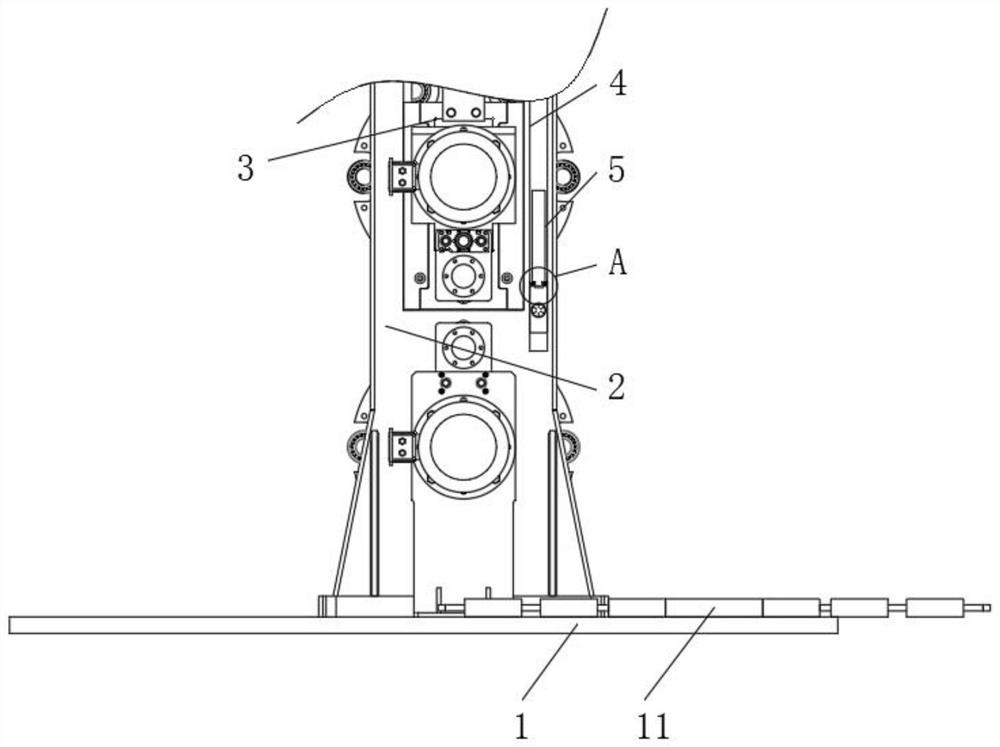
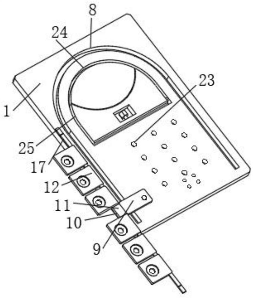
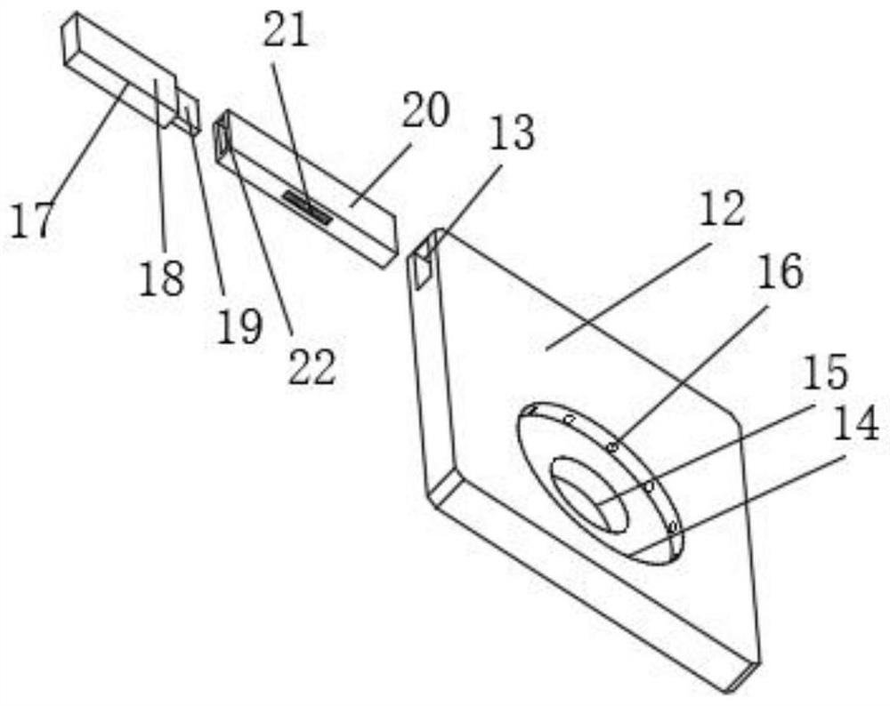
[0004] The purpose of the present invention is to provide a quick-change device for roll change that can be used to assemble roll materials, so as to solve the problem that the existing quick-change device proposed in the background technology has a single end space due to the lack of development and design at the end. It has not been fully utilized. For example, the arc-shaped bend is not designed at the end, and it is equipped with a movable material storage mechanism. As a result, when it replaces the mold group, the material cannot be retrieved in time, the efficiency is low, and it is also difficult to change the material. There is no good auxiliary loading mechanism for temporary storage, and there is a situation of poor practicability

Method used


Image

  • Quick change device capable of carrying out roll material packaging for roll change
  • Quick change device capable of carrying out roll material packaging for roll change
  • Quick change device capable of carrying out roll material packaging for roll change

Examples


Embodiment Construction

[0026] The following will clearly and completely describe the technical solutions in the embodiments of the present invention with reference to the accompanying drawings in the embodiments of the present invention. Obviously, the described embodiments are only some, not all, embodiments of the present invention.

[0027] In the description of the present invention, unless otherwise stated, the meaning of "plurality" is two or more; the terms "upper", "lower", "left", "right", "inner", "outer" , "front end", "rear end", "head", "tail", etc. indicate the orientation or positional relationship based on the orientation or positional relationship shown in the drawings, and are only for the convenience of describing the present invention and simplifying the description, rather than Nothing indicating or implying that a referenced device or element must have a particular orientation, be constructed, and operate in a particular orientation should therefore not be construed as limiting ...


PUM


Abstract

The quick-changing device comprises a floor and a curve, a supporting stand column is arranged at the upper end of the floor, a mold set is installed in the middle of the supporting stand column, a column groove is formed in the end wall of the supporting stand column, a core strip is arranged at the inner side end of the column groove, a lower sliding piece is installed at the bottom end of the core strip, and the lower sliding piece is connected with the lower sliding piece. A lower sliding piece is arranged on the upper end wall of the floor, a lock catch screw penetrates through the end wall of the lower sliding piece, the bend is formed in the upper end wall of the floor, a joint piece is arranged at the end of the bend, and a material collecting mechanism is installed at the side end of the joint piece and comprises a plywood, a material plate, a penetrating cavity, an outer groove, an inner groove and a groove hole. The quick-changing device has the beneficial effects that the caliber of the outer groove is larger than that of the inner groove, when the quick-changing device is used, the end of a to-be-changed mold set directly penetrates into the outer groove to be static, the penetrating cavity is communicated with the outer groove through the groove hole, liquid can conveniently flow into the outer groove from the penetrating cavity through the groove hole, and the quick-changing device is convenient to use. And maintenance liquid can be conveniently conveyed.

Description

technical field [0001] The invention relates to the technical field of roll changing devices, in particular to a quick changing device for roll changing that can assemble roll materials. Background technique [0002] The steel pipe cold bending forming unit in the form of flat and vertical rolls is used to produce a steel pipe of one specification. It can replace a complete set of corresponding roll mold sets. During the roll replacement process, it is often necessary to design the entire refueling device. [0003] Because the end of the existing quick change device has not been developed and designed, the end space is single and not fully utilized. For example, the end is not designed with an arc-shaped curve, and it is equipped with a movable storage mechanism, which leads to the replacement of the mold. When the module is assembled, it is impossible to take the material in time, the efficiency is low, and there is no good auxiliary loading mechanism for temporary storage ...

Claims


Application Information

Patent Timeline
IPC IPC(8): B21D7/08B21D7/16B21D9/10B21D9/16B21D37/04B21D37/18
Inventor 杨剑蒋毅杨庆元程深圳周锡隆
Owner 江苏大东图科技有限公司
Learn More