Stator for rotary electric machine

A technology for rotating electrical machines and stators, applied to the shape/style/structure of winding conductors, which can solve the problems of difficulty in satisfying the positional accuracy of multiple fastening parts, insufficient joint strength, and increased manufacturing costs to achieve guaranteed joints Effects of strength, suppression of increase in manufacturing cost, and suppression of increase in the number of parts

Active Publication Date: 2016-11-09
HONDA MOTOR CO LTD
View PDF6 Cites 6 Cited by
  • Summary
  • Abstract
  • Description
  • Claims
  • Application Information

AI Technical Summary

Problems solved by technology

[0009] However, in the case of joining the slot coil and the connection coil by fastening, it is difficult to satisfy the positional accuracy of the protrusions and holes in the plurality of fastening parts, and it may not be possible to obtain sufficient joint strength, or to make the joint Intensity Deviation
[0010] In addition, if it is desired to improve the positional accuracy of the protrusions and holes in the plurality of fastening parts to the required level, the manufacturing cost may increase due to the increase in processing costs.

Method used


Image

  • Stator for rotary electric machine
  • Stator for rotary electric machine
  • Stator for rotary electric machine

Examples


Embodiment Construction

[0077] Hereinafter, an embodiment of a stator of a rotating electrical machine according to the present invention will be described based on the drawings. It should be noted that the drawings are viewed along the direction of the symbols.

[0078] [stator]

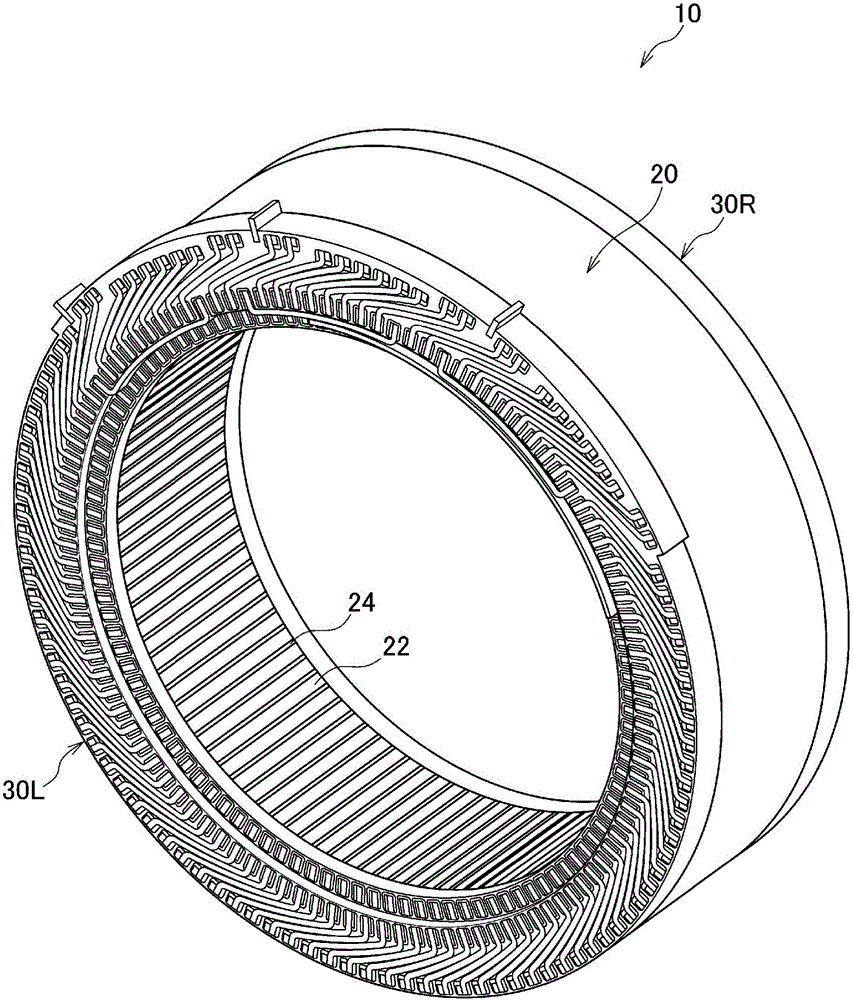
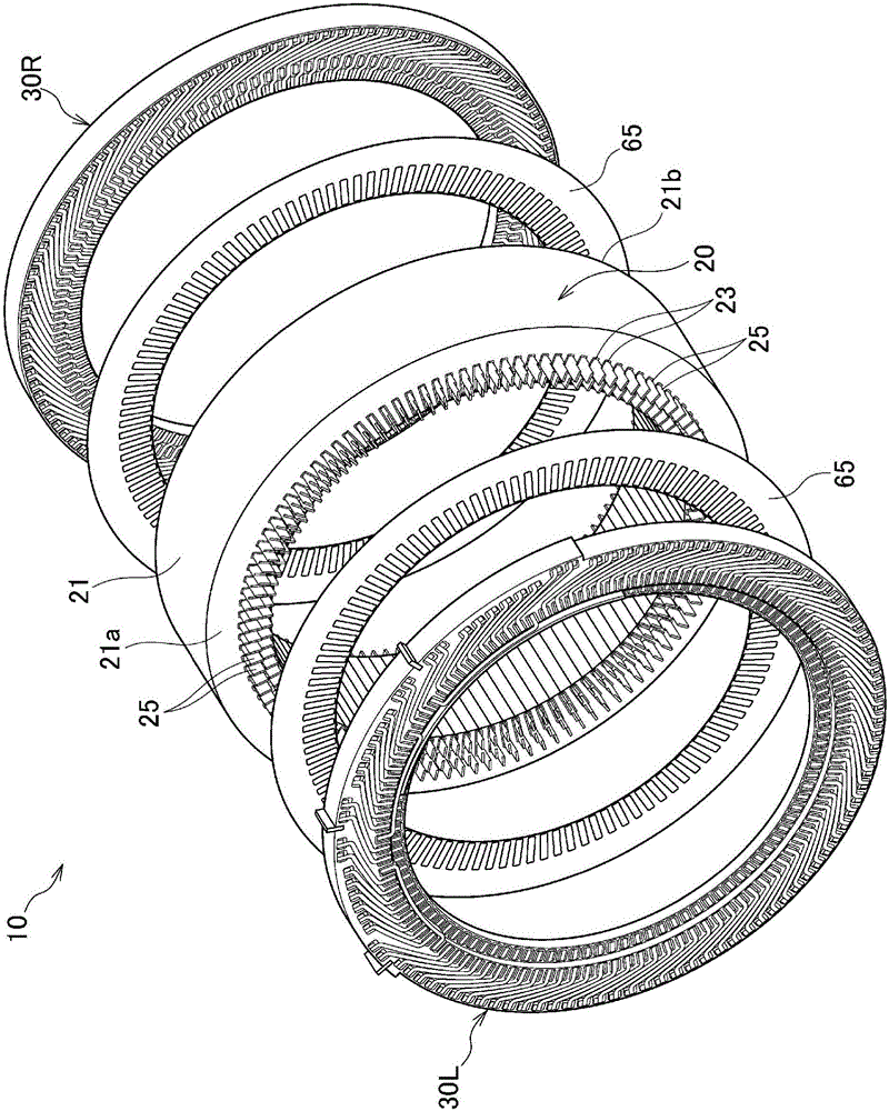
[0079] Such as figure 1 and figure 2 As shown, the stator 10 of the rotating electrical machine according to this embodiment includes a stator core assembly 20 and a pair of base plate assemblies 30L, 30R. The base plate assemblies 30L, 30R are arranged and assembled on both sides of the stator core assembly 20 . An insulating sheet 65 such as a silicon wafer is arranged between the stator core assembly 20 and the base plate assemblies 30L, 30R to insulate the stator core assembly 20 and the base plate assemblies 30L, 30R.

[0080] [1 stator core assembly]

[0081] The stator core assembly 20 includes a stator core 21 and a plurality (108 in the illustrated embodiment) of slot coils 25 .

[0082] [1-1 stator core]

...


PUM


Abstract

Provided is a stator (10) in which a coil (50) comprises a plurality of slot coils (25) that are inserted in a slot (23) and a plurality of connection coils (40) that connect the slots coils (25) to each other further on the outside in the axial direction than the axial end surface of a stator core (21). The slot coils (25) and the connection coils (40) are formed from a plate-shaped conductor that comprises a flat plate surface that intersects the plate thickness direction. The plate surfaces of the plate-shaped conductors are arranged opposite each other with said surfaces in contact and joined at the contact surfaces (P2, P3) of the slot coils (25) and the connection coils (40).

Description

technical field [0001] The present invention relates to a stator that can be mounted on a rotating electric machine such as an electric vehicle, a hybrid vehicle, or the like. Background technique [0002] Conventionally, a stator of a rotating electrical machine is known in which a coil is formed by winding a winding around teeth of a stator core. In a conventional rotating electric machine in which coils are produced by winding windings on the teeth of the stator core, the windings and the stator core need to be handled separately, and the windings are wound while sandwiching insulating paper, so the winding process is troublesome, and due to the insulating paper, etc., so proper insulating performance may not be ensured. [0003] Therefore, in recent years, rotating electric machines using segmented coils have been proposed as stators of other rotating electric machines. For example, in the stators of the rotating electric machines described in Patent Documents 1 and 2,...

Claims


Application Information

Patent Timeline
IPC IPC(8): H02K3/28
CPCH02K3/12H02K3/28H02K3/32
Inventor 壹岐友贵
Owner HONDA MOTOR CO LTD
Why Eureka
Try Eureka