Compressor And Method For Manufacturing Compressor

A manufacturing method and compressor technology, which is applied in the field of compressors, can solve problems such as deformation and deformation of airtight containers, and the decrease in reliability of compression units in airtight containers, and achieve the effect of suppressing the increase in manufacturing costs

Inactive Publication Date: 2016-03-16
MITSUBISHI ELECTRIC CORP
View PDF14 Cites 9 Cited by
  • Summary
  • Abstract
  • Description
  • Claims
  • Application Information

AI Technical Summary

Problems solved by technology

Therefore, since the flange and the airtight container are pressed against each other, there is a possibility of causing deformation of the airtight container
In addition, since the suction connection pipe on which the flange is formed is connected to the compression unit, there is a possibility that deformation may occur in the compression unit when the flange is pressed.
In this way, the compressor described in Patent Document 2 has the problem that the airtight container and the compression unit are deformed, resulting in a decrease in reliability.

Method used


Image

  • Compressor And Method For Manufacturing Compressor
  • Compressor And Method For Manufacturing Compressor
  • Compressor And Method For Manufacturing Compressor

Examples


Embodiment approach 1

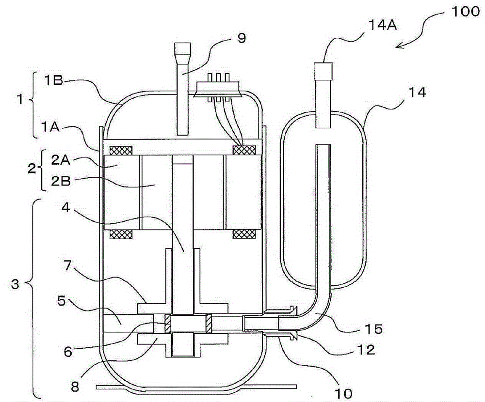
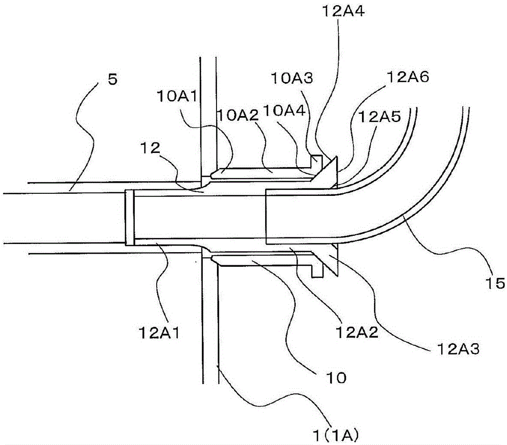
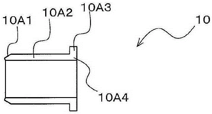
[0047] figure 1 It is a sectional view schematically showing the structure of the compressor 100 according to the first embodiment. figure 2 is schematically shown figure 1 A cross-sectional view of the engagement of the suction connection pipe 12 and the junction pipe 10 of the compressor 100 is shown. Figure 3A ~ Figure 3D It is a schematic diagram explaining the structure of the junction pipe 10 etc., and the 1st welding part P. FIG. refer to figure 1 , figure 2 , Figure 3A ~ Figure 3D The configuration of the compressor 100 will be described. also, figure 1 , figure 2 , Figure 3A ~ Figure 3D It is a longitudinal sectional view of various structures.

[0048] [Structure description]

[0049] Such as figure 1 As shown, the compressor 100 has: a closed container 1; an electric unit 2; a compression unit 3; and an accumulator 14 for accumulating liquid refrigerant. In addition, the compressor 100 has a junction pipe 10 connected to the airtight container 1 , ...

Embodiment approach 2

[0116] Figure 7 It is a cross-sectional view schematically showing the connection between the suction connecting pipe 120 and the joint pipe 110 of the compressor 100 according to the second embodiment. Figure 8A It is a schematic diagram explaining the structure of the joint pipe 110 . Figure 8B It is a schematic diagram explaining the structure of the suction connection pipe 120. refer to Figure 7 , Figure 8A as well as Figure 8B Compressor 100 according to Embodiment 2 will be described. In addition, in this Embodiment 2, the same code|symbol is attached|subjected to the structure common to Embodiment 1, and it demonstrates centering on a difference.

[0117] In Embodiment 1, the first welded portion P is formed on the contact surface between the inner diameter corner portion 10A4 of the joint pipe 10 and the tapered portion 12A4 of the suction connection pipe 12 . On the other hand, in Embodiment 2, instead of forming the inner diameter corner portion 10A4 in t...


PUM


Abstract

The invention aims at providing a compressor and a method for manufacturing the compressor for inhibiting cost increase and reliability reduction. A compressor comprises: a sealed container; a compression element provided within the sealed container and compressing a refrigerant; an electric motor element provided within the sealed container and driving the compression element; a joint pipe consisting of iron, the joint pipe having one end connected to the sealed container; a suction connection pipe consisting of iron, the suction connection pipe being inserted in the joint pipe and having one end connected to the compression element; and a suction pipe having one end connected to the other end of the suction connection pipe. The suction connection pipe has an annular first protrusion formed on the other end thereof and protruding from the inner peripheral side to the outer peripheral side. In the suction connection pipe and the joint pipe, the first protrusion of the suction connection pipe and the other end of the joint pipe are joined.

Description

technical field [0001] The present invention relates to a compressor and a method for manufacturing the compressor. Background technique [0002] Among the existing compressors, there is proposed a compressor that has: a suction connection pipe, one end of which is connected to the cylinder of the compression mechanism; a joint pipe, which is connected to a closed container, and A suction connection pipe is inserted; and a suction pipe to which the other end of the suction connection pipe is connected (for example, refer to Patent Document 1). In the compressor described in Patent Document 1, the junction pipe is made of copper, and the suction connection pipe and the junction pipe are fixed by brazing. [0003] In addition, among the existing compressors, there has been proposed a compressor having: a suction connection pipe connected to the cylinder of the compression mechanism; and an airtight container formed with a suction connection. The opening into which the tube i...

Claims


Application Information

Patent Timeline
Patent Type & Authority Applications(China)
IPC IPC(8): F04B39/12F04B35/04
CPCF04B39/12F04B39/14F04C29/00F04C29/12
Inventor 赤堀康之
Owner MITSUBISHI ELECTRIC CORP
Why Eureka
Try Eureka