Clamping jig and system for inspecting spacer grids for nuclear fuel assembly

一种核燃料组件、定位格架的技术,应用在燃料元件的组装、核工程、核能发电等方向,能够解决工作效率低下等问题,达到提高作业效率的效果

Active Publication Date: 2012-04-04
KEPCO NUCLEAR FUEL CO LTD
View PDF3 Cites 7 Cited by
  • Summary
  • Abstract
  • Description
  • Claims
  • Application Information

AI Technical Summary

Problems solved by technology

Known fixtures can only hold certain types of spacer grids, making work inefficient as only one spacer grid can be loaded and measured at a time

Method used


Image

  • Clamping jig and system for inspecting spacer grids for nuclear fuel assembly
  • Clamping jig and system for inspecting spacer grids for nuclear fuel assembly
  • Clamping jig and system for inspecting spacer grids for nuclear fuel assembly

Examples


Embodiment Construction

[0047] Preferred embodiments of the present invention will be described in detail below in conjunction with the accompanying drawings.

[0048] First of all, the terms and words used in this specification and claims are not limited by the usual or dictionary meanings, but should be properly defined as the terms used by the inventor to best describe the present invention, based on technical principles, and Interpretation is the meaning and concept contained in the technical idea of ​​the present invention.

[0049] Therefore, the embodiments described in this specification and the structures shown in the accompanying drawings are only the most preferred embodiments of the present invention, and do not represent all technical ideas of the present invention. Various equivalents and modifications of the contents.

[0050] Hereinafter, description with reference to drawings is as follows.

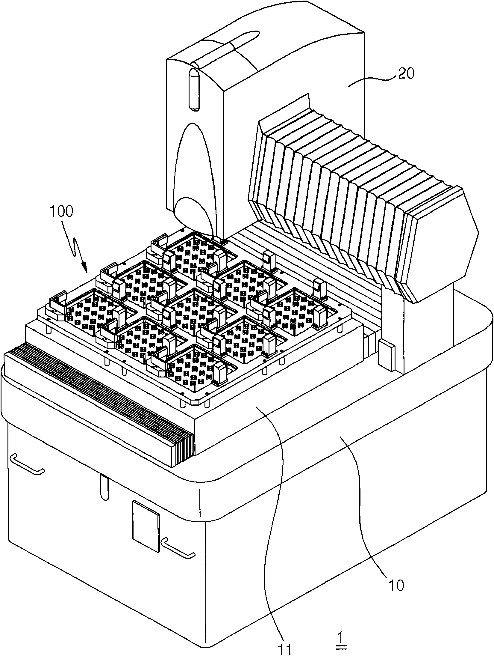
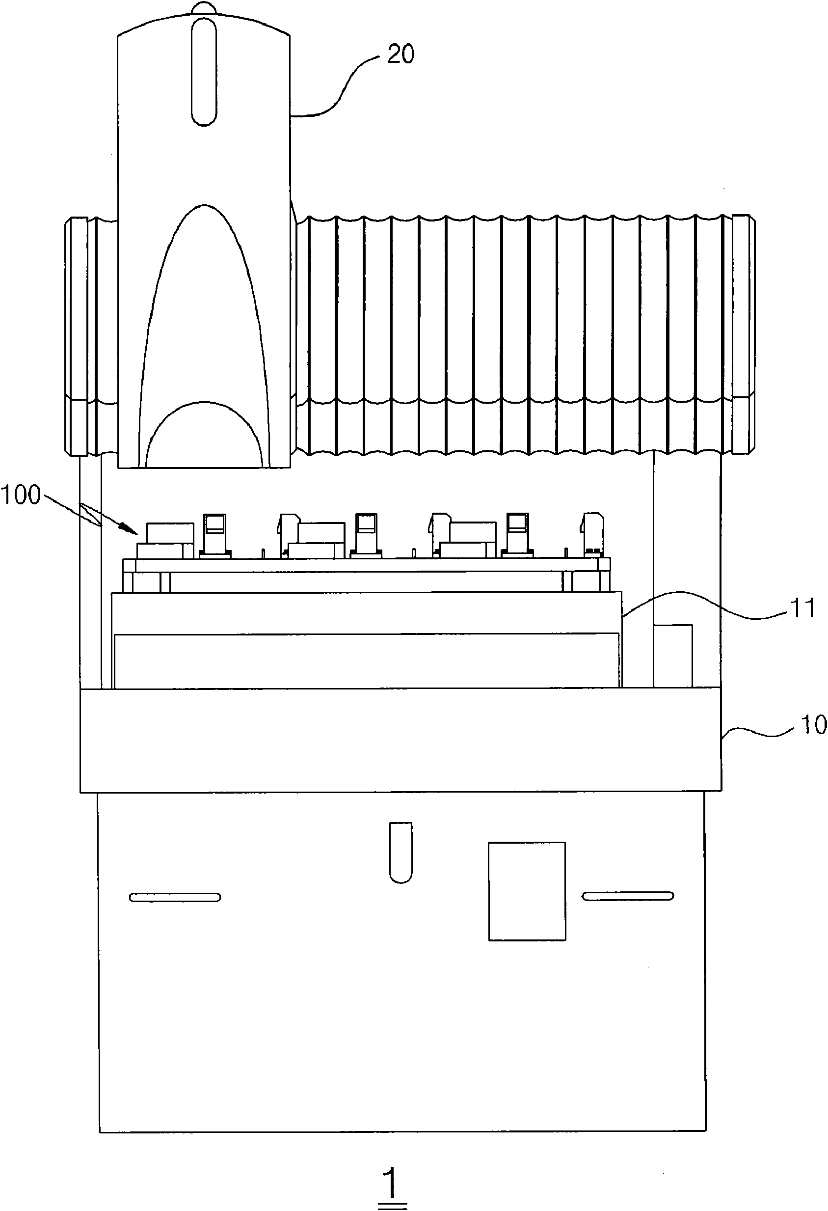
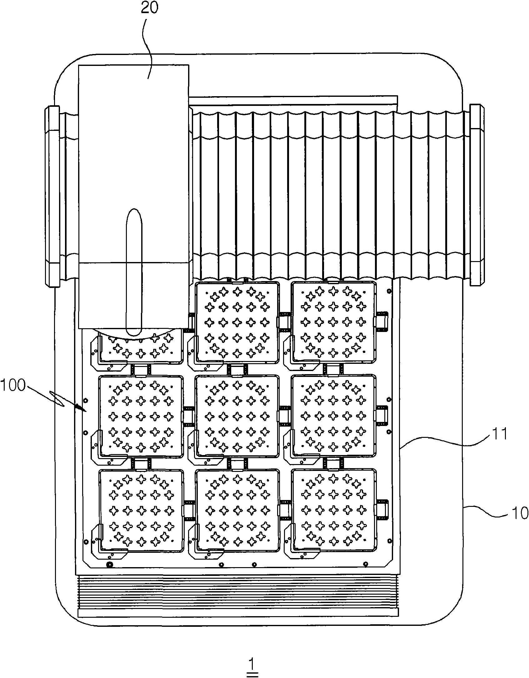
[0051] Such as Figure 1 to Figure 3 As shown, the nuclear fuel assembly positioning grid...


PUM


Abstract

The invention relates to a clamping jig and a system for inspecting spacer grids for a nuclear fuel assembly. The jig firmly and precisely clamps a variety of spacer grids on a measurement stage moving at high speed using a non-contact measurer. The clamping jig includes a frame having a plurality of holding recesses into which the corresponding spacer grids are inserted, supporting means mounted in each holding recess of the frame to allow each spacer grid to be adjusted from below so it can be maintained in a horizontal state, clamping means installed around each holding recess to clamp two adjacent sides of each spacer grid to a corner of the respective holding recess, and resilient means installed on the sides opposite the clamping means and resiliently supporting the other two sides of each spacer grid. According to the present invention, the variety of spacer grids having flexible shape or size can be held by the clamping jig of the invention, so that a plurality of spacer grids can be inspected at a time. As a result, it is possible to improve work efficiency.

Description

technical field [0001] The invention relates to a fixing jig and a measuring device for measuring the positioning grid of a nuclear fuel assembly. The fixing jig and the measuring device are used to check the positioning grid in the nuclear fuel assembly, and a non-contact measuring device is used to measure and support the platform at high speed. (Stage) can firmly and precisely fix spacers of various shapes. Background technique [0002] In general, the positioning grid is made of grid plates formed by springs and honeycombs arranged horizontally and vertically and compiled, and welded at the intersection to support and fix the nuclear fuel rods. [0003] At present, the commercially available positioning grids are basically welded by laser welding (Laser Welding) or brazing (Brazing) to the lattice body. In order to support the nuclear fuel rods, springs and honeycombs are formed on the four sides of all the units of the positioning grid. The position and shape of the sp...

Claims


Application Information

Patent Timeline
Patent Type & Authority Applications(China)
IPC IPC(8): G21C17/00
CPCG21C17/06G21C3/34Y02E30/40Y02E30/30
Inventor 孙岁翼金亨燮金石俸丁海均金龙泰韩甲辰
Owner KEPCO NUCLEAR FUEL CO LTD
Why Eureka
Try Eureka