
Copper foil cutter

A cutting machine, copper foil technology, applied in metal processing and other directions, can solve the problems of difficult knife adjustment, short tool life, small cutting range, etc., to achieve convenient knife adjustment and maintenance, stable tool performance, and neat cutting face. Effect

Inactive Publication Date: 2012-04-11
浙江安浦科技有限公司
View PDF0 Cites 5 Cited by
  • Summary
  • Abstract
  • Description
  • Claims
  • Application Information

AI Technical Summary

Problems solved by technology

There are usually three ways to cut copper foil. The first one is ordinary scissors. The disadvantage is that although the structure is simple, the cutting range is small, the opening angle is large, and it is unsafe. It is rarely used at present; the second one is the knife. The disadvantage of fixed upper knife and vertical down cutting is that the structure of the device is complicated, it is difficult to adjust the knife, and the cost is high; the third type, the lower knife is fixed and the upper knife is cut down in an arc, the disadvantage is that the knife edge is worn, the life of the knife is short, and the structure is complicated

Method used


Image

  • Copper foil cutter
  • Copper foil cutter
  • Copper foil cutter

Examples


Embodiment Construction

[0020] The present invention will be described in further detail below in conjunction with the accompanying drawings.

[0021] This specific embodiment is an explanation of the present invention, not a limitation of the present invention. Those skilled in the art can make any amendments to this embodiment as required after reading this description, but as long as they are within the scope of the claims of the present invention, they are all subject to patent protection. legal protection.

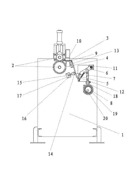
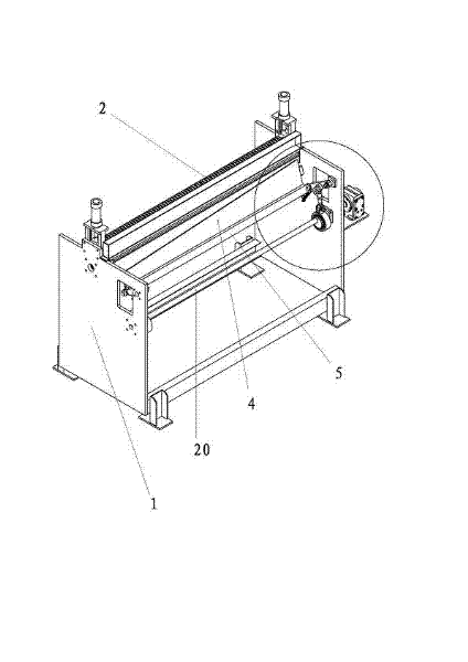
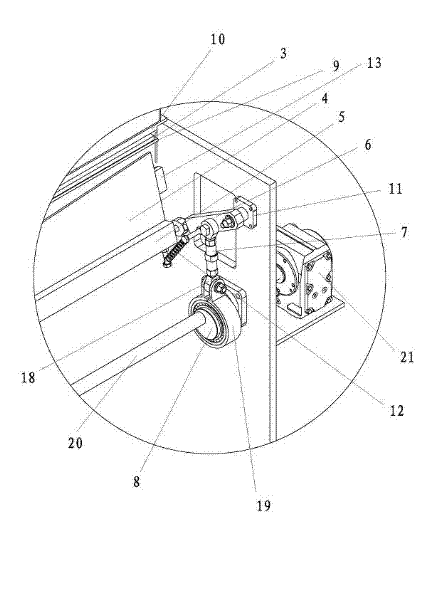
[0022] Such as Figure 1~3 As shown, a copper foil cutting machine includes a frame 1, a cutting mechanism and a copper foil pinch mechanism; the copper foil pinching mechanism includes a pair of pinch rollers 2; the cutting mechanism includes an upper knife 3 and a lower knife 4 And the action assembly; the action assembly includes the lower knife seat 5, the swing rod 6, the ejector rod 7, and the eccentric wheel 8; between the upper knife 3 and the lower knife 4, there is a copper foil p...


PUM


Abstract

The invention discloses a copper foil cutter, which comprises a frame, a cutting mechanism and a copper foil clamping and conveying mechanism, wherein the cutting mechanism comprises an upper knife, a lower knife and an acting assembly for driving the lower knife; and a horizontal copper foil platform is arranged between the upper knife and the lower knife. Compared with the prior art, the copper foil cutter has the advantage that: the positions of a movable cutting edge and a fixed cutting edge are switched, i.e., an upper cutting edge is taken as a fixed cutting edge while a lower cutting edge is taken as a movable cutting edge, so that the complexity of a cutting device is lowered; and the lower cutting edge and the upper cutting edge are always in point contact with each other during cutting, so that sheets can be better cut. Meanwhile, the copper foil cutter further has the advantages of low manufacturing cost, efficient production, ordered cut end face, no dust falling, stable tool performance, convenience for tool adjustment and maintenance, and the like.

Description

technical field [0001] The invention relates to the technical field of cutting machines, in particular to a copper foil cutting machine. Background technique [0002] Copper clad laminates are the basic materials of the electronics industry. In order to meet the needs of manufacturing copper-clad laminates, electronic-grade copper foil (purity above 99.7%, thickness 5um-105um) is often cut into sheets. There are usually three ways to cut copper foil. The first one is ordinary scissors. The disadvantage is that although the structure is simple, the cutting range is small, the opening angle is large, and it is unsafe. It is rarely used at present; the second one is the knife. The disadvantage of fixed upper knife and vertical down cutting is that the device structure is complex, difficult to adjust the knife, and the cost is high; the third type, the lower knife is fixed and the upper knife is cut down in an arc, the disadvantage is that the knife edge wears a lot, the tool l...

Claims


Application Information

Patent Timeline
Patent Type & Authority Applications(China)
IPC IPC(8): B26D1/04B26D5/18
Inventor 金玉成周灵珍
Owner 浙江安浦科技有限公司
Learn More