Variable flat plate type bionic leading edge flap device

A leading edge flap, flat-plate technology, applied in transportation and packaging, aircraft parts, aircraft control, etc., can solve problems such as processing difficulties, increase resistance, etc., to prevent flight safety accidents, improve lift coefficient, and improve maneuverability. Effect

Active Publication Date: 2012-04-11
BEIHANG UNIV
View PDF5 Cites 10 Cited by
  • Summary
  • Abstract
  • Description
  • Claims
  • Application Information

AI Technical Summary

Problems solved by technology

[0006] The purpose of the present invention is to solve the problem that the traditional three-dimensional wavy bionic leading edge increases the resistance during cruising and the processing is difficult. A new variable flat-plate bionic leading edge flap device is invented. Without increasing the flight resistance in the cruising state, Improve the stall performance of the aircraft, increase its lift coefficient after stall, and the processing and installation are simple and convenient

Method used


Image

  • Variable flat plate type bionic leading edge flap device
  • Variable flat plate type bionic leading edge flap device
  • Variable flat plate type bionic leading edge flap device

Examples


Embodiment Construction

[0026] The technical solutions of the present invention will be further described below in conjunction with the accompanying drawings and embodiments.

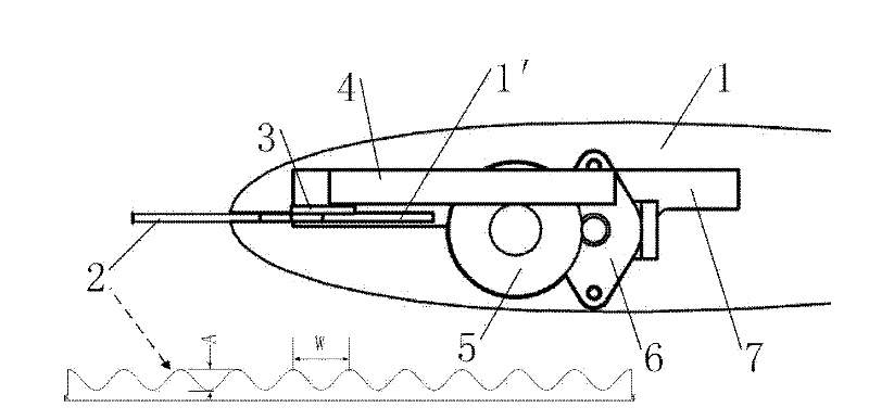
[0027] Such as figure 1 As shown, a variable flat-plate bionic leading edge flap device of the present invention is composed of three parts: the bionic leading edge flap (2), the leading edge flap storage chamber (1') and the telescopic actuating mechanism. The bionic leading edge flap (2) is placed in the leading edge flap storage cavity (1') at the leading edge of the wing, and is connected with the telescopic actuating mechanism. The telescopic actuating mechanism is driven by a first-stage reduction gear (5) rack (4) mechanism driven by a micro-stepping motor (6), which enables the bionic leading edge flap (2) to be freely extended and recovered.

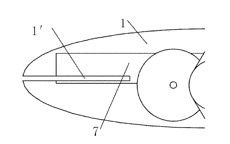
[0028] Such as figure 2 As shown, it is a partially enlarged schematic diagram of the leading edge flap storage cavity (1'), which is a rectangular opening along the chord li...


PUM


Abstract

The invention discloses a variable flat plate type bionic leading edge flap device, which comprises a bionic leading edge flap, a leading edge flap receiving cavity and a telescopic drive mechanism; the bionic leading edge flap is placed in the leading edge flap receiving cavity on the leading edge of a wing and is connected with the telescopic drive mechanism; the telescopic drive mechanism is driven by a rack mechanism driven by a micro step motor; the bionic leading edge flap has a similar sine curve shape, and the bionic leading edge flaps with different performances can be obtained by changing wavelength and amplitude; the leading edge flap receiving cavity is used for receiving the bionic leading edge flap; the telescopic drive mechanism is composed of a step motor, a first speed reduction gear, a rack and a connecting piece; the step motor is mounted in the wing and is engaged with the high speed end of the first speed reduction gear; the rack is placed in a sliding groove on the wing and is engaged with the low speed end of the first speed reduction gear; and the rack is connected with the bionic leading edge flap through the connecting piece. The lift coefficient of the airplane after stalling angle of attack is increased and maneuvering performance of the airplane is greatly improved.

Description

(1) Technical field [0001] The invention relates to a variable plate-type bionic leading edge flap and a matching expansion device, which can effectively improve the use angle of attack and maneuverability of an aircraft, and belongs to the field of bionic flow control. (2) Background technology [0002] Aircraft increase lift by increasing the aircraft's angle of attack, that is, the angle between the wing and the incoming flow. But when the angle of attack increases to a certain range, the flow on the upper surface of the wing will separate, causing the lift coefficient to drop sharply and the drag coefficient to rise sharply, that is, the so-called "stall" phenomenon occurs, which endangers flight safety. In order to prevent flight safety problems caused by stalls, the general approach is to limit the angle of attack of military / civilian aircraft, that is, the aircraft is not allowed to fly outside the range of the safe angle of attack. Therefore, increasing the range of ...

Claims


Application Information

Patent Timeline
Patent Type & Authority Applications(China)
IPC IPC(8): B64C9/22
Inventor 王晋军陈皇潘翀
Owner BEIHANG UNIV
Why Eureka
Try Eureka