Novel parafoil and steering and control method thereof

A control method and parafoil technology, applied to parachutes, aircraft parts, transportation and packaging, etc., can solve the problems of high weight cost, limited control ability, and low control accuracy, and achieve weight reduction, small control force, and high control accuracy Effect

Inactive Publication Date: 2014-03-26
AEROSPACE LIFE SUPPORT IND LTD
7 Cites 9 Cited by

AI-Extracted Technical Summary

Problems solved by technology

[0004] The technical problem to be solved by the present invention is to provide a new stamping parafoil and its manipulation control method for the proble...

Method used

[0029] The shape of the guide vane 1 is similar to that of the guide hole 2, and the area of ​​the guide vane 1 is lar...

Abstract

The invention provides a novel parafoil and a steering and control method thereof. The parafoil comprises upper wing surfaces, lower wing surfaces, a plurality of wing ribs, two groups of parafoil ropes, two groups of steering ropes, two groups of straphangers and two steering straps. A plurality of flow guide holes are formed on two sides of each upper wing surface symmetrically, a flow guide vane is arranged on the inner side of each upper wing surface and at the position corresponding to each flow guide hole, a plurality of steering rope holes and the steering ropes penetrating the steering rope holes are arranged on two sides of each lower wing surface symmetrically, each flow guide vane is arranged between each upper wing surface and the corresponding lower wing surface, and each flow defector is connected with the corresponding steering rope. The steering ropes are stretched to drive the flow guide vanes to fold and unfold so as to control opening and closing of the flow guide holes, and directional steering and flared landing steering are realized. The novel parafoil has the advantages that aerodynamic performance of the parafoil is changed through the structures of the flow guide vanes, the flow guide holes and the steering ropes, weight of an existing steering mechanism is reduced greatly, steering force is low, the directional steering and the flared landing steering are realized simultaneously, and control accuracy is high.

Application Domain

Parachutes

Technology Topic

Image

  • Novel parafoil and steering and control method thereof
  • Novel parafoil and steering and control method thereof
  • Novel parafoil and steering and control method thereof

Examples

  • Experimental program(1)

Example Embodiment

[0027] The present invention will be described in detail below in conjunction with the accompanying drawings and embodiments.
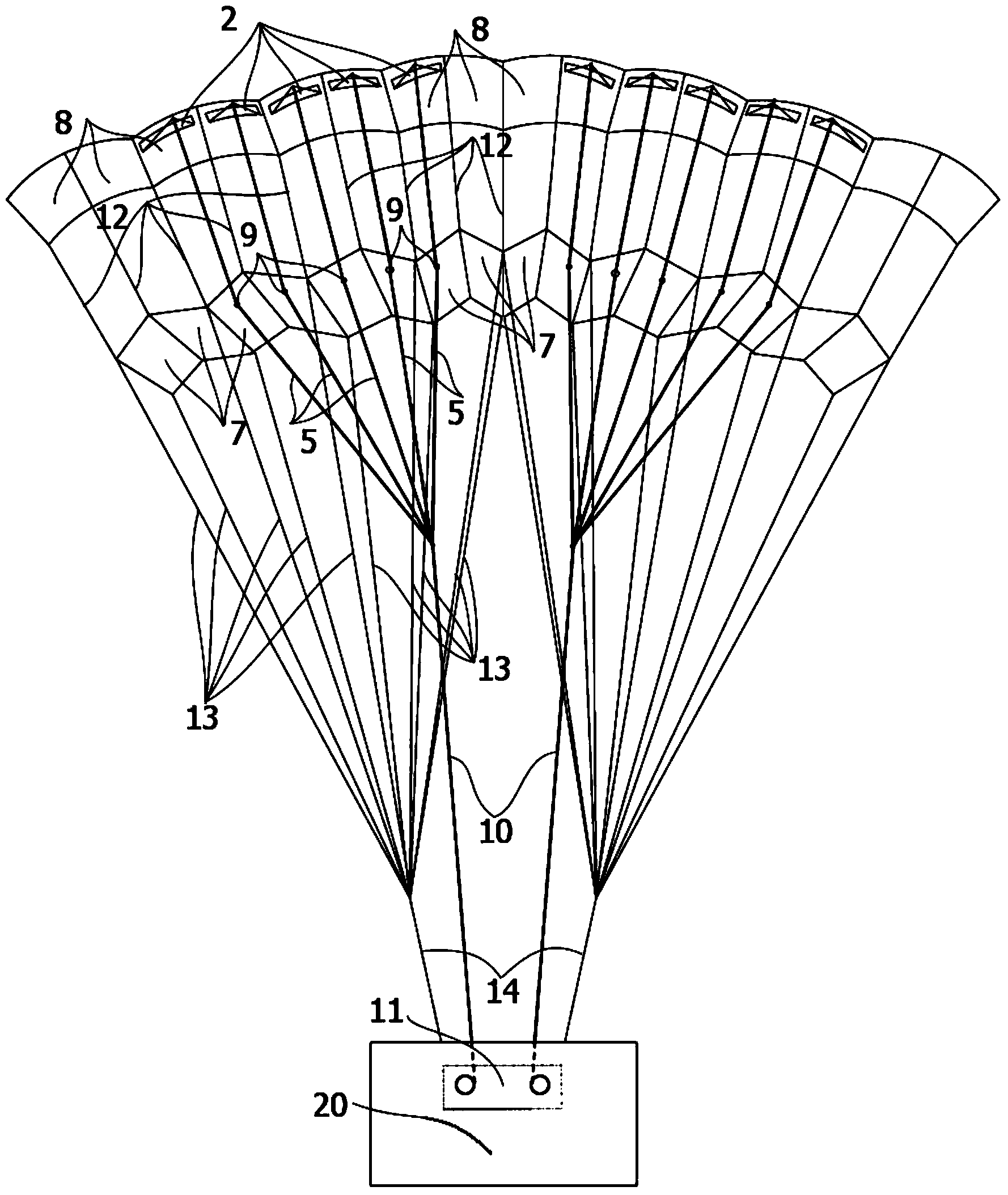
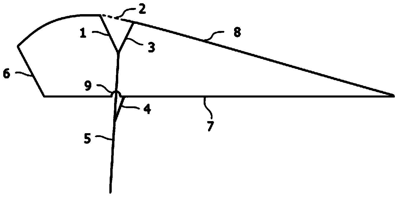
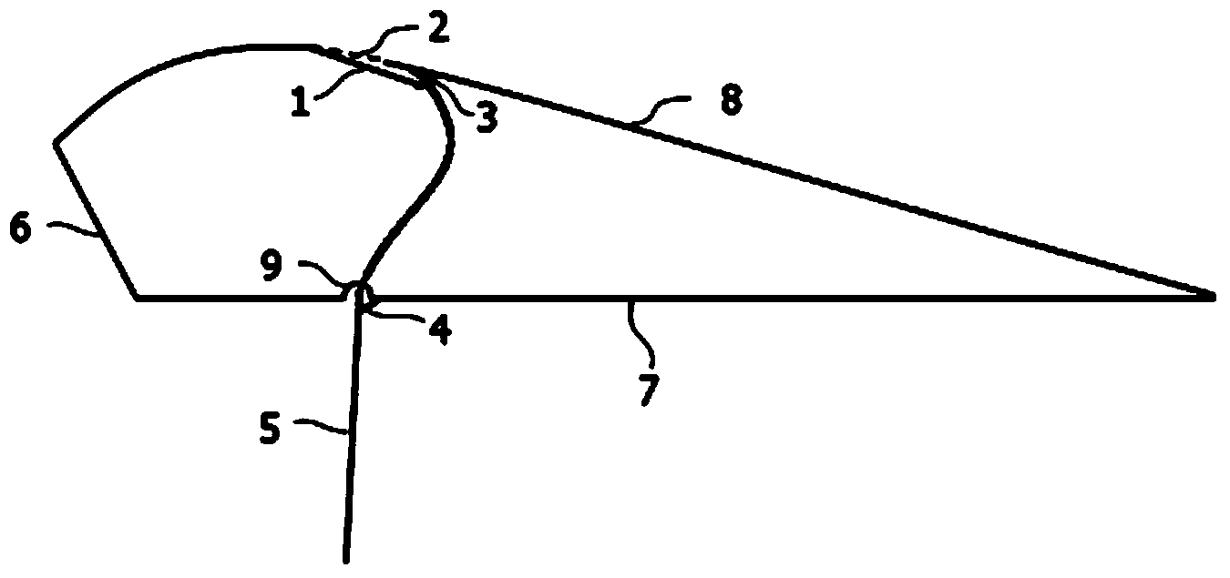
[0028] refer to Figure 1 to Figure 5 As shown, the novel stamping parafoil described in the present invention comprises an upper airfoil 8, a lower airfoil 7, a plurality of ribs 12, two groups of parachute ropes 13, two groups of control ropes 5, two groups of slings 14, two A control belt 10, the trailing edge of the upper airfoil 8 is connected to the trailing edge of the lower airfoil 7, the ribs 12 are parallel to each other, and the two ends of each rib 12 are connected to the upper airfoil 8 and the lower airfoil respectively. 7 connection, every two ribs 12 and the space between the upper airfoil 8 and the lower airfoil 7 form an air chamber with a leading edge opening 6; a number of diversion holes 2 are symmetrically arranged on both sides of the upper airfoil 8, A deflector 1 is arranged on the inner side of the upper airfoil 8 corresponding to each guide hole 2, and each deflector 1 is arranged between the upper airfoil 8 and the lower airfoil 7; the lower airfoil 7 and two groups The umbrella rope 13 is connected, and the umbrella rope 13 is connected to the load 20 through the sling 14; a number of control rope holes 9 are arranged symmetrically on both sides of the lower airfoil 7, and one end of each control rope 5 passes through the control rope hole 9 on the corresponding side and The deflector 1 is connected, and the other ends of the plurality of control ropes 5 meet and then are connected to the control mechanism 11 through a control belt 10 , and the control mechanism 11 is connected to the load 20 .
[0029] The shape of the guide vane 1 is similar to that of the guide hole 2, and the area of ​​the guide vane 1 is larger than that of the guide hole at the corresponding position, so as to ensure the sealing effect of the closure.
[0030] The two groups of control ropes 5 are arranged symmetrically on both sides of the parafoil
[0031] The number of the control rope holes 9 is equal to the number of the guide holes 2 .
[0032] The upper airfoil 8 is provided with a deflector return belt 3 connected with the deflector 1, and the lower airfoil 7 is provided with a control rope return belt 4 connected with the control rope 5, and the guide The piece return belt 3 and the control rope return belt 4 are used to overcome the resistance received under the slack state of the control rope 5 when the diversion hole 2 is closed, and prevent the guide vane 1 from opening under resistance.
[0033] The control method of the novel stamping parafoil of the present invention, a plurality of guide holes 2 are symmetrically arranged on both sides of the upper airfoil 8 of the parafoil, and a guide vane is arranged on the inner side of the upper airfoil 8 corresponding to each guide hole 2 1. A number of control rope holes 9 and control ropes 5 passing through the control rope holes 9 are arranged symmetrically on both sides of the lower airfoil 7 of the parafoil, and each deflector 1 is arranged between the upper airfoil 8 and the lower airfoil 7 , and the deflector 1 is connected with the control rope 5; the opening and closing of the deflector 1 is driven by stretching the control rope 5, and the opening and closing of the deflector hole 2 are controlled, so as to realize the steering control and bird drop control of the parafoil ,details as follows:
[0034] 1) When the guide vanes 1 on both sides of the upper airfoil 8 are opened at the same time, the guide holes 2 on both sides are opened at the same time, so that the gas in the air chamber of the stamped parafoil is discharged from the guide holes 2 to the outside of the upper airfoil 8, which is equivalent to the upper airfoil 8. The virtual spoilers on both sides of the airfoil 8 are opened, which greatly increases the drag of the parafoil, reduces the lift-to-drag ratio, and realizes the bird-down maneuver;
[0035] 2) When only the upper airfoil 8 unilateral deflector 1 is opened, the unilateral airfoil 2 is opened, so that the gas in the air chamber of the parafoil is discharged from the airfoil 2 to the outside of the upper airfoil 8, which is equivalent to the upper airfoil 8 The virtual spoiler on one side is opened to increase the resistance on one side of the parafoil, generate turning moment, and realize steering control;
[0036] 3) When the diversion holes 2 on the upper airfoils 8 on both sides are closed, the aerodynamic performance of the entire parafoil remains consistent with that of the traditional parafoil without any manipulation.
[0037] exist figure 1 Among them, the installation relationship between the guide hole 2, the guide vane 1 and the upper airfoil 8 and the lower airfoil 7, the guide hole 2 is arranged on the upper airfoil 8 on each side of the parafoil, and the guide vane 1 is arranged on the upper and lower wings of the parafoil. Between the surfaces, it is installed on the upper airfoil 8.
[0038] exist figure 2 Among them, when the deflector 1 is opened, the control rope 5 is in a tensioned state, the deflector 1 is in an open state, and the upper airfoil 8 guide hole 2 is in an open state, forming a virtual deflector state, and the deflector return belt 3 and the control rope return belt 4 are in the pulling state, and now the deflector 1 is in the open state, which rapidly and effectively increases the aerodynamic resistance on the open side of the parafoil, thereby realizing the parafoil drop control or steering control.
[0039] exist image 3In the middle, when the deflector 1 is closed, the control rope 5 is not manipulated, the deflector 1 and the guide hole 2 of the upper airfoil 8 basically fit together, and the return belt 3 of the guide vane and the return belt 4 of the control rope are in a contracted state. At this time , the whole parafoil is basically the same as the original parafoil. The control rope 5 is in a relaxed state, and now the overall aerodynamic performance of the parafoil remains consistent with that of the traditional parafoil, without any manipulation.
[0040] exist Figure 4 and Figure 5 In the above, the specific working process of the guide vane 1 is as follows: the opening of the guide vane 1 is controlled by the operating rope 5, and the shape of the guide vane 1 and the guide hole 2 on the upper surface of the parafoil are consistent, but the area and size of the guide vane 1 are uniform. Larger than the guide hole 2 on the upper airfoil, to ensure the sealing effect of the guide vane 1 closing, the control rope 5 passes through the control rope hole 9 of the lower wing surface 8, and is connected with the control mechanism 11.
[0041] The above descriptions are only preferred embodiments of the present invention, and are not intended to limit the present invention. Any modifications, equivalent replacements and improvements made within the spirit and principles of the present invention should be included in the protection of the present invention. within range.

PUM

no PUM

Description & Claims & Application Information

We can also present the details of the Description, Claims and Application information to help users get a comprehensive understanding of the technical details of the patent, such as background art, summary of invention, brief description of drawings, description of embodiments, and other original content. On the other hand, users can also determine the specific scope of protection of the technology through the list of claims; as well as understand the changes in the life cycle of the technology with the presentation of the patent timeline. Login to view more.

Similar technology patents

Parking mechanism and vehicle

InactiveCN112977368ASmall control forceImprove comfortHand actuated initiationsMechanical braking transmissionAutomotive engineeringBrake force
Owner:BEIJING BORGWARD AUTOMOBILE CO LTD

Motor vehicle lock

PendingCN114008284AImprove reverse couplingSmall control forcePower-actuated vehicle locksAutomotive engineeringElectrical and Electronics engineering
Owner:BROSE SCHLIESSSYSTEME GMBH & CO KG

Classification and recommendation of technical efficacy words

  • Small control force
  • High control precision

Parking mechanism and vehicle

InactiveCN112977368ASmall control forceImprove comfortHand actuated initiationsMechanical braking transmissionAutomotive engineeringBrake force
Owner:BEIJING BORGWARD AUTOMOBILE CO LTD

Motor vehicle lock

PendingCN114008284AImprove reverse couplingSmall control forcePower-actuated vehicle locksAutomotive engineeringElectrical and Electronics engineering
Owner:BROSE SCHLIESSSYSTEME GMBH & CO KG

Control Method and Device For Engine

Owner:SHANDONG SHENPU TRAFFIC TECHNOLOGY CO LTD
Why Eureka
Try Eureka