Wheel turning sling of high speed motor train unit

A high-speed EMU and wheel technology, applied in the field of flipping spreaders, can solve problems such as low production efficiency and large safety hazards in the operation process, and achieve the effects of improving production efficiency, improving production safety, and shortening the required time

Active Publication Date: 2012-04-11
ZHIBO LUCCHINI RAILWAY EQUIP
View PDF8 Cites 21 Cited by
  • Summary
  • Abstract
  • Description
  • Claims
  • Application Information

AI Technical Summary

Problems solved by technology

[0003] The invention provides a wheel turning spreader for high-speed EMUs, which solves the problems of low production efficiency and great potential safety hazards in the operation process in the prior art where the wheel needs to be replaced twice for turning over once.

Method used


Image

  • Wheel turning sling of high speed motor train unit
  • Wheel turning sling of high speed motor train unit
  • Wheel turning sling of high speed motor train unit

Examples


Embodiment Construction

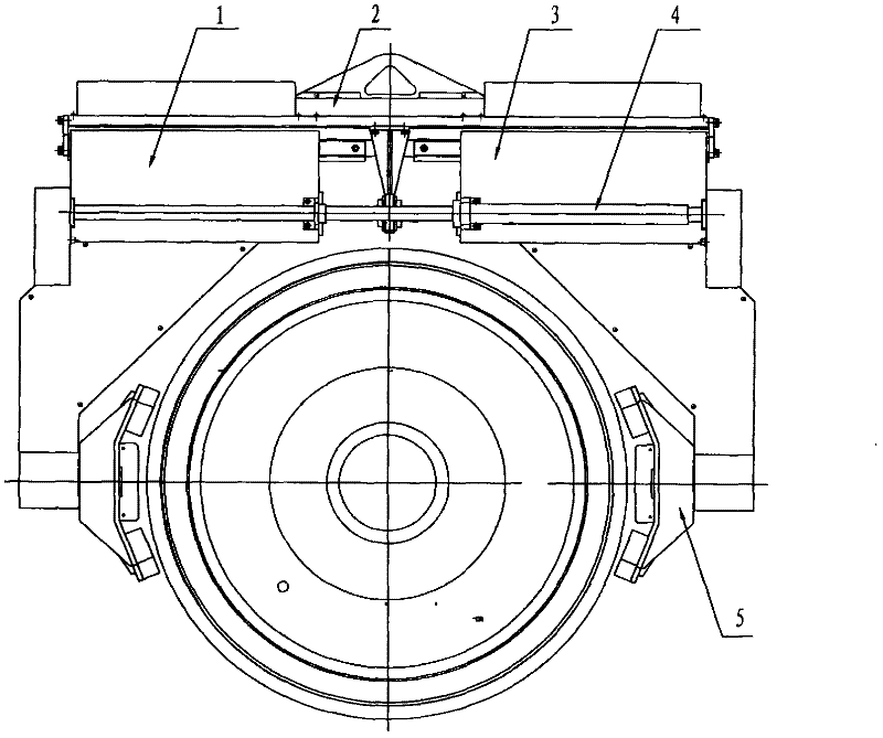
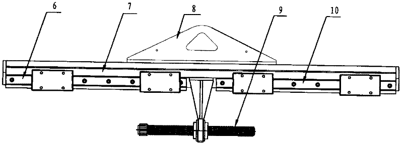
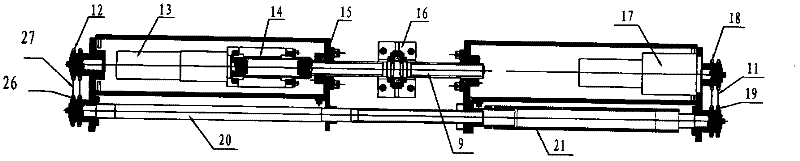
[0012] A high-speed EMU wheel turning spreader, comprising a suspension beam 2, a left suspension arm 1, a right suspension arm 3, a claw 5 and a transmission mechanism 4, a left guide rail 6 is arranged on the left part of the beam 7 of the suspension beam 2, and the The right part of crossbeam 7 is provided with right guide rail 10, and left guide rail 6 and right guide rail 10 are arranged on a straight line, is provided with leading screw 9 in the screw bearing seat 16 of the middle part of crossbeam 7, and the left part screw thread of leading screw 9 It is arranged in the opposite direction with the right threaded button. A left lead screw nut 15 is arranged on the left side of the lead screw 9, a right lead screw nut is arranged on the right part of the lead screw 9, and the left lead screw nut is movable with the left guide rail. The left boom 1 on 6 is fixedly connected, the right lead screw nut is fixedly connected with the right boom 3 which is movably arranged on th...


PUM


Abstract

The invention discloses a wheel turning sling, which solves the problem that the sling needs to be replaced for two times in turning over the wheel once in the prior art. The wheel turning sling comprises a lifting beam (2), left and right lifting arms and a transmission mechanism (4); a screw rod (9) is disposed in a screw rod bearing seat (16) in the middle of a transverse beam (7); screw rod nuts are disposed at both sides of the screw rod (9); the screw rod nuts are fixedly connected with the lifting arms movably disposed on guide rails; jaws (5 ) are correspondingly disposed at the lowerends of the left and right lifting arms (1 and 3); one end of the screw rod (9) is fixedly connected with the output shaft of a clamping speed reducing motor (13) through a spline housing (14); a rotary speed reducing motor (17) and the clamping speed reducing motor (13) are arranged on the lifting arm (2); a right rotary double chain wheel (18) is disposed on the output shaft of the rotary speedreducing motor (17); and chains are disposed among a jaw turning chain wheel, a rotary active chain wheel and a force transmission chain wheel. The wheel turning time is shortened by the wheel turning sling.

Description

technical field [0001] The invention relates to an overturning spreader for wheels of a high-speed EMU. Background technique [0002] In the wheel production of the existing high-speed EMUs, due to the different processing procedures of the wheels, the placement posture of the wheels needs to be changed frequently. There are three placement postures of the wheels that need to be placed horizontally, vertically and obliquely. The existing wheel spreader can only realize the lifting and lowering of the wheel, and the wheel cannot be turned over at a certain angle during the lifting process. When the wheel needs to be placed in a different position, a soft sling is usually used to pass through the center hole of the wheel Lift it and place it on a specific platform, and then use other spreaders to lift the wheel and place it at the designated position. Therefore, it is necessary to replace the spreader twice once the wheel is turned over, which has the problems of low producti...

Claims


Application Information

Patent Timeline
Patent Type & Authority Applications(China)
IPC IPC(8): B66C1/44B66C13/08
Inventor 杨怀文李明章麻万春马大琨何振洪王长峰刘春生霍锋锋
Owner ZHIBO LUCCHINI RAILWAY EQUIP
Why Eureka
Try Eureka