Supercharge Your Innovation With Domain-Expert AI Agents!

General purpose gantry crane

A gantry crane and gantry technology, applied in the direction of hoisting equipment braking devices, load hanging components, bottom support structures, etc., can solve the problem of increased span value of cranes, inability of wheels to fall on rails, and inability to realize heavy load steering, etc. problem, to achieve the effect of simple and simple force, ensuring safety and reliability

Inactive Publication Date: 2012-04-11
ZHENGZHOU NEW DAFANG HEAVY IND & TECH
View PDF10 Cites 1 Cited by
  • Summary
  • Abstract
  • Description
  • Claims
  • Application Information

AI Technical Summary

Problems solved by technology

The existing gantry crane gantry structure cannot realize heavy-load steering, especially for large-span and high-height gantry cranes, it is even more difficult to realize heavy-load steering
The reason is that the steering of the gantry crane under heavy load conditions will cause the deformation of the main girder and cause downward deflection, and the two outriggers will generate a horizontal lateral force. For the double rigid leg gantry crane, this horizontal force cannot be overcome. Yes, when the gantry crane turns to move laterally, the span value of the crane will increase due to this horizontal force, and when it turns again, the increase in the span value will prevent the wheels on the trolley from falling on the rails
The larger the span, the higher the lifting height, the greater the lifting weight, and the greater the change in the span value, so the double rigid leg gantry crane cannot realize heavy load steering

Method used


Image

  • General purpose gantry crane
  • General purpose gantry crane
  • General purpose gantry crane

Examples


Embodiment Construction

[0024] The present invention will be further described below in conjunction with embodiment (accompanying drawing)

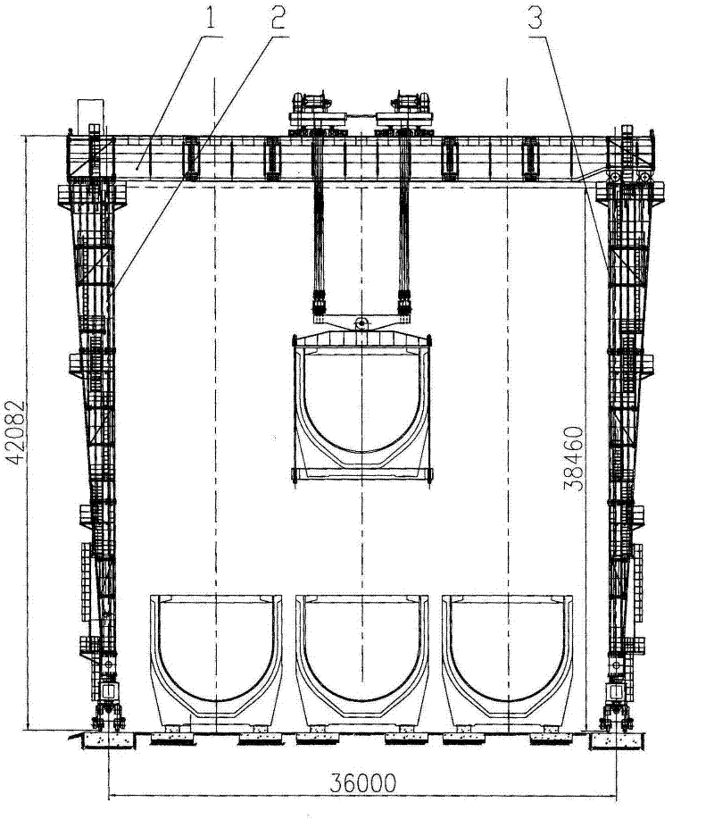
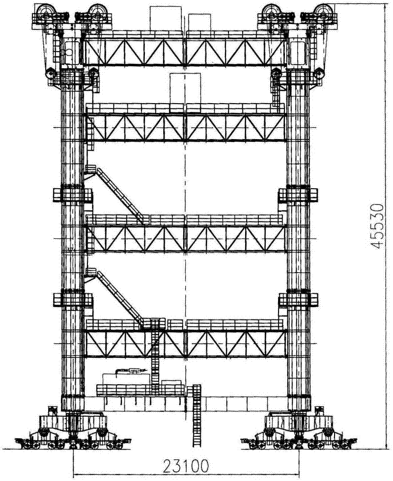
[0025] Such as figure 1 , 2 shown. The general-purpose gantry crane of the present invention comprises a gantry girder 1, and supporting legs positioned at both sides of the gantry main girder, one side of the described two side supporting legs is a rigid supporting leg 2, and the other side supporting leg Using semi-rigid legs 3, the rigid legs 2 are consolidated with the main beam 1 of the mast frame through connecting bolts, and the upper ends of the semi-rigid legs 3 are respectively welded to the main beam 1 of the mast frame and the semi-rigid legs The mutually matched supporting leg hinge seats on the 3 are combined with the main girder 1 of the main frame in a hinged manner.

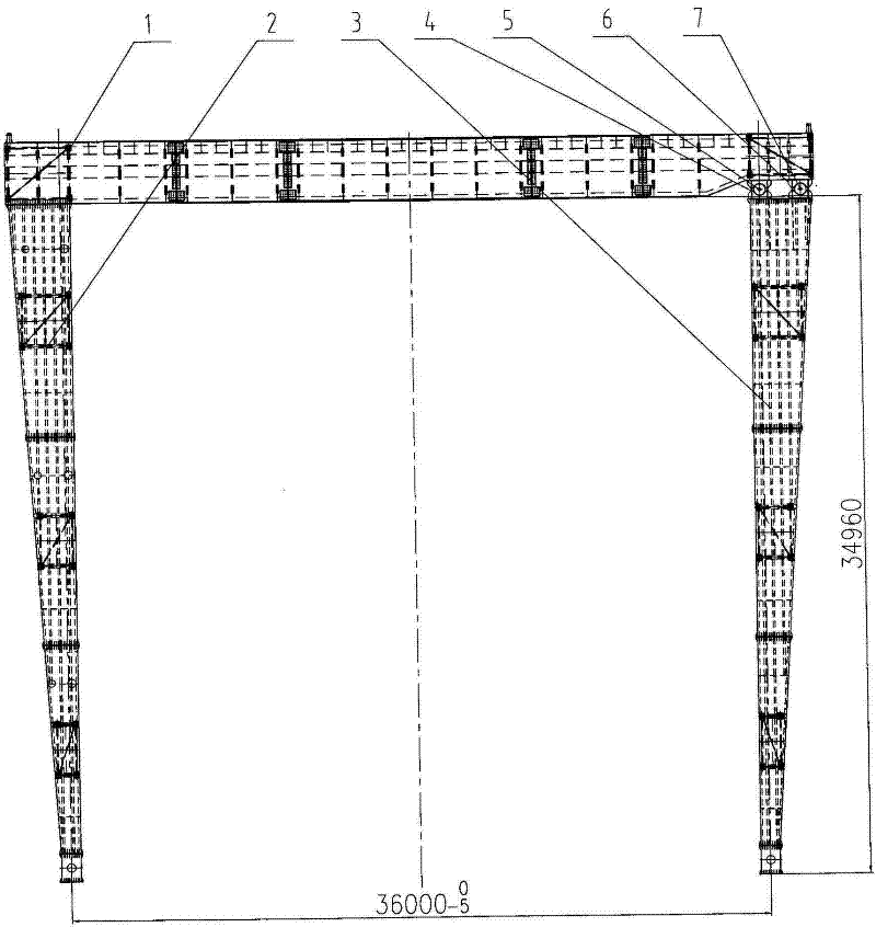
[0026] Such as image 3 , 4 , 5, 6, and 7, the leg hinge seat described in the present invention includes: the leg inner hinge composed of two groups of front and rear inner u...


PUM


Abstract

The invention relates to a general purpose gantry crane which comprises a gantry girder and legs which are arranged at two sides of the gantry girder. The crane is characterized in that the leg at one side of the legs at two sides is a rigid leg, and the other leg is a semi-rigid leg; the rigid leg is fixedly connected with the gantry girder through a connecting bolt; and the upper end of the semi-rigid leg is combined with the gantry girder through hinged supports which are respectively welded on the gantry girder and the semi-rigid leg and matched with each other, in a mode of hinge jointing.

Description

technical field [0001] The invention relates to a general gantry crane. Background technique [0002] General-purpose gantry cranes are widely used. In order to maximize the utilization of equipment and reduce production costs, many gantry cranes have a steering function, which can realize multi-area hoisting construction, but these steerings are empty, especially for large-tonnage gantry cranes. type crane. The existing gantry crane gantry structure cannot realize heavy-load steering, especially for large-span and high-height gantry cranes, it is even more difficult to realize heavy-load steering. The reason is that the steering of the gantry crane under heavy load conditions will cause the deformation of the main girder and cause downward deflection, and the two outriggers will generate a horizontal lateral force. For the double rigid leg gantry crane, this horizontal force cannot be overcome. Yes, when the gantry crane turns to do lateral movement, the span value of the...

Claims


Application Information

Patent Timeline
Patent Type & Authority Applications(China)
IPC IPC(8): B66C5/02
Inventor 高自茂陈德利林建青代宇贾力锋张艳丽苏春霞于洪云宫占斌
Owner ZHENGZHOU NEW DAFANG HEAVY IND & TECH
Features
  • R&D
  • Intellectual Property
  • Life Sciences
  • Materials
  • Tech Scout
  • Unparalleled Data Quality
  • Higher Quality Content
  • 60% Fewer Hallucinations
Learn More