Flue gas waste heat recovery device

A recovery device and flue gas waste heat technology, applied in the direction of air heaters, fluid heaters, climate sustainability, etc., can solve the problems of ineffective recovery of water vapor condensation latent heat, narrow application range, waste of heat energy, etc., to achieve good environmental protection Effect, improve heat conversion efficiency, prolong the effect of residence time

Active Publication Date: 2013-07-24
WUXI XIZHOU MACHINERY
View PDF4 Cites 0 Cited by
  • Summary
  • Abstract
  • Description
  • Claims
  • Application Information

AI Technical Summary

Problems solved by technology

[0003] In the prior art, most of the heating surfaces such as boilers and water heaters use partition wall heat exchange after fuel combustion, which cannot effectively recover the latent heat of condensation of water vapor, resulting in waste of heat energy
Although there is also a waste heat recovery device that can directly contact the mixed flue gas, it is an integral boiler with a relatively complicated structure, and it is only suitable for large-capacity and high-pressure parameters on large-scale oil-fired and coal-fired industrial boilers. , with a narrow scope of application

Method used


Image

  • Flue gas waste heat recovery device
  • Flue gas waste heat recovery device
  • Flue gas waste heat recovery device

Examples


Embodiment Construction

[0017] The present invention will be further described below in conjunction with specific drawings and embodiments.

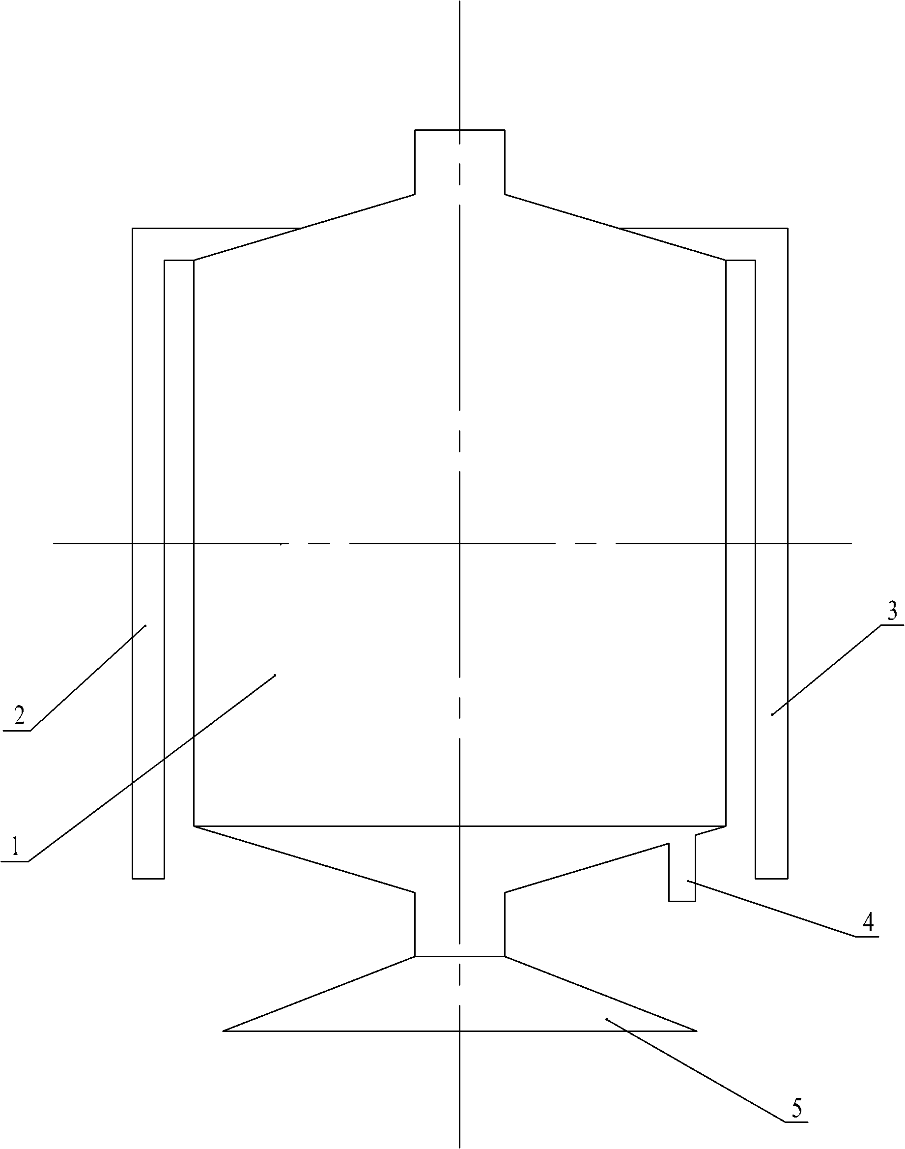
[0018] As shown in the figure: the flue gas waste heat recovery device in the embodiment mainly includes three parts: the main cylinder body 1, the heat conversion unit and the flue gas distributor 9. The main cylinder body 1 is a hollow cylindrical structure, and the main cylinder body A smoke distributor 9 is arranged at the bottom, and the smoke distributor 9 communicates with the smoke inlet device 5 below it, and the heat conversion unit is arranged above the smoke distributor 9.

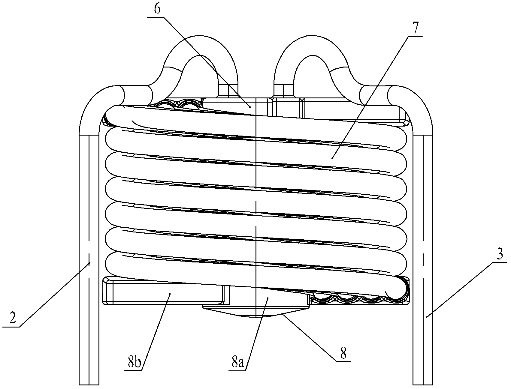
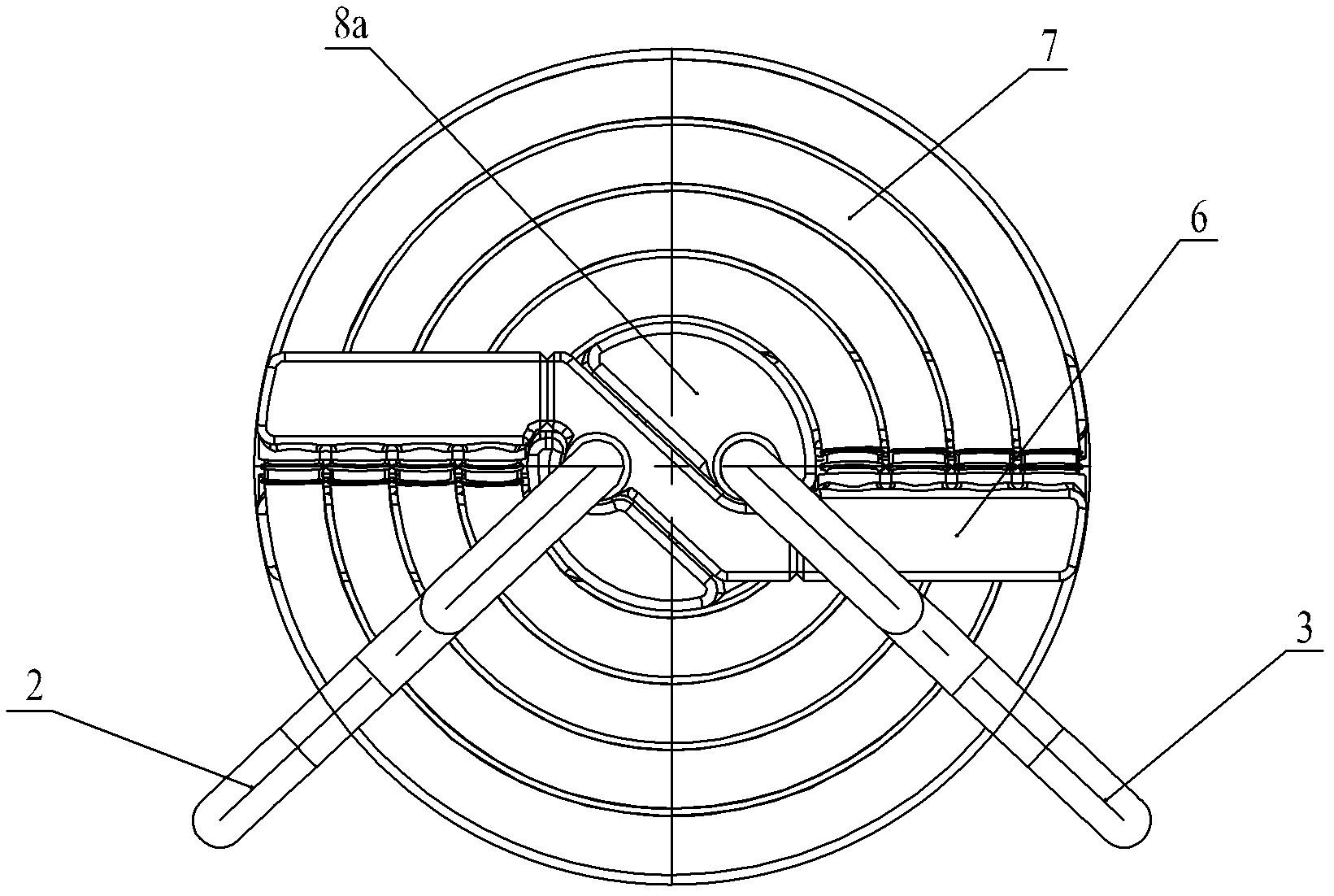
[0019] Such as figure 2 , image 3 As shown, the heat conversion unit is mainly composed of a cold water storage body 6, a hot water storage body 8 and heat exchange components. The heat exchange components in the embodiment are composed of eight concentrically arranged spiral coils 7, and the eight spiral coils 7 are equally divided into four groups according to different ra...


PUM


Abstract

The invention relates to a flue gas waste heat recovery device, which comprises a main cylinder, wherein the main cylinder is hollow inside; a heat conversion unit is arranged in the main cylinder; and the bottom end of the main cylinder is connected with a flue gas inlet device. The flue gas waste heat recovery device is characterized in that: the main cylinder is cylindrical, wherein the bottomof the main cylinder is provided with a flue gas distributor, the flue gas distributor is communicated with the flue gas inlet device, and the heat conversion unit is arranged above the flue gas distributor; the heat conversion unit comprises a cold water storage body, a hot water storage body and a heat exchange component, wherein the cold water storage body is externally connected with a water inlet pipeline, and a hot water outlet is externally connected with a water outlet pipeline; and the bottom of the main cylinder is provided with a condensed water outlet. The flue gas waste heat recovery device is suitable for non-industrial occasions, such as families, markets, hosts, restaurants and the like and has the advantages of simple structure, wide application range and capability of deeply utilizing heat in flue gas and potential heat energy in the flue gas; and core components of the flue gas waste heat recovery device are made of stainless steel materials, so that not only scale prevention capability of the product can be enhanced, service life is prolonged, but also quality of domestic water can be ensured.

Description

technical field [0001] The invention belongs to the field of heat energy recovery and reuse, and relates to a heat energy recovery and reuse device, in particular to a flue gas waste heat recovery device for recovering flue gas waste heat in a heat exchange manner. Background technique [0002] At present, the temperature of the flue gas produced by the combustion of conventional fuels (including coal, oil and natural gas) is relatively high, and there is a considerable part of heat energy in the flue gas, especially the heat energy contained in the flue gas containing high-enthalpy water vapor is relatively high. high. If the high-temperature flue gas is directly discharged into the atmosphere through the chimney without treatment, it will cause a great waste of heat energy, especially the latent heat of condensation of the water vapor in the flue gas has not been effectively utilized, and the heat carried by the water vapor is the heat of the exhaust gas. A large part of ...

Claims


Application Information

Patent Timeline
Patent Type & Authority Patents(China)
IPC IPC(8): F24H8/00F24H9/00F24H9/18
CPCY02B30/102Y02B30/00
Inventor 包建忠
Owner WUXI XIZHOU MACHINERY
Why Eureka
Try Eureka