Phase interferometer direction finding method for ambiguity resolution by extension baselines

A phase interferometer and deblurring technology, which is used in direction determination direction, radio wave measurement systems, instruments, etc., can solve the problems of high calculation amount, low utilization of array element information, inaccurate direction finding, etc. The effect of direction finding accuracy, improving the efficiency of the direction finding system, and reducing the amount of calculation

Inactive Publication Date: 2012-04-11
UNIV OF ELECTRONIC SCI & TECH OF CHINA
2 Cites 50 Cited by

AI-Extracted Technical Summary

Problems solved by technology

[0005] Aiming at the technical problems of inaccurate direction finding and high calculation amount caused by the low utilizat...

Method used

The method of the present invention is to utilize triangular array to solve circular array ambiguity as coarse measurement array, and carry out DOA estimation by each array element of circular array, has fully utilized the information of each array element, has further improved direction-finding precision. At the same time, the new algorithm not only reduces the calculation amount in the defuzzification process by calculating the intermediate quantity of the direction cosine, but compared with the correlation method, which needs to calculate the incident angle value once for each fuzzy phase group, the new algorithm only calculates The value of the incident angle is improved once, which greatly reduces the calculation a...

Abstract

The invention belongs to the technical field of communication radar. An equilateral triangular array is selected as a rough measurement array in a circular array, the phase difference between two baselines in a triangular matrix is calculated, and possible actual phase differences are exhaustively listed according to the maximum ambiguity degree; the possible actual phase differences are substituted to a circular array phase difference solving formula to build a phase difference vector sample library; the ambiguity degree of the actual circular array phase difference is obtained by a related operation, and further an actual circular array phase difference vector is obtained; and finally, an incident angle value as an accurate DOA (Direction of Arrival) estimate is inversely solved by finding the least squares solution of direction cosine. The novel phase interferometer two-dimensional direction finding algorithm for ambiguity resolution by extension baselines is applied, so that higher precision can be obtained compared with a direction finding algorithm based on a related operation, and the required amount of computation is greatly reduced. The method is a high-performance angle measurement algorithm.

Application Domain

Direction finders

Technology Topic

Image

  • Phase interferometer direction finding method for ambiguity resolution by extension baselines
  • Phase interferometer direction finding method for ambiguity resolution by extension baselines
  • Phase interferometer direction finding method for ambiguity resolution by extension baselines

Examples

  • Experimental program(1)

Example Embodiment

[0029] The specific embodiments of the present invention will be described in detail below with reference to the accompanying drawings of the specification.
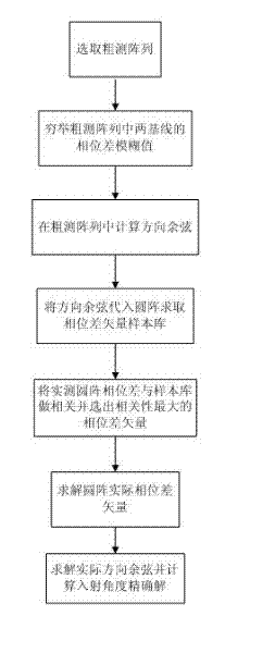
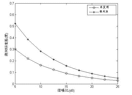
[0030] The present invention provides a phase interferometer direction finding method based on the idea of ​​correlation method to resolve ambiguity. Through the present invention, the two-dimensional direction finding accuracy of the correlation interferometer can be improved, while reducing the amount of calculation and improving the performance of the direction finding system. Direction finding performance.
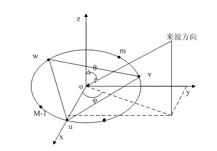
[0031] The present invention mainly selects a triangular array from the circular array. First, the direction cosine is solved by the phase difference between the elements of the triangular array, and then the direction cosine is substituted into the phase difference theoretical calculation formula of the circular array, and the circular array is completed through correlation operations. Unblur, finally solve the exact value of the incident angle.
[0032] For the convenience of description, first define the following:
[0033] Phase interferometer: Phase interferometer direction finding refers to the method of calculating the direction of signal arrival based on the measured spatial phase difference between the electromagnetic waves arriving at each element.
[0034] Sample library: The sample library is a collection of vectors composed of the signal incident on the antenna array from different angles, and the phase difference generated between different elements.
[0035] Similarity function: The similarity function is used to quantitatively describe the mapping relationship of the similarity between two vectors. The input of this mapping is the two vectors to be found for similarity, and the output is the similarity.
[0036] A phase interferometer direction finding method with extended baseline defuzzification, the flow chart is as follows figure 1 As shown, it specifically includes the following steps:
[0037] Step 1 Select an equilateral triangle in the circular array as the rough measurement array, and the two sides of the triangle are two baselines, and find the ambiguity phase difference between the two baselines , , Exhaustively obtain the ambiguity phase difference of the two baselines Group ambiguity;
[0038] among them: , Is the baseline length, Is the incident signal wavelength, Means rounding up, , ,;
[0039] Step 2 Use the Group ambiguity phase difference is obtained in triangular matrix Cosine;
[0040] Step 3 will Substitute into the formula for calculating the phase difference between the elements of the circular array Phase difference vector , Where each element is the phase difference between two array elements;
[0041] Step 4 Obtain the measured phase difference vector between the elements of the circular array , Where each element is the actual measured phase difference between the two array elements;
[0042] Step 5 Combine the results obtained in step 3 Phase difference vector As a sample, and the measured phase difference vector in step 4 For correlation operations, the similarity function is:
[0043]
[0044] among them, Is the length of the phase difference vector;
[0045] Step 6 Select the phase difference vector sample with the greatest similarity in Step 5, and record it as , Calculate the defuzzification value of the measured phase difference vector, namely
[0046]
[0047] among them Represents rounding to integer.
[0048] Step 7 Use the actual phase difference vector calculated in Step 6 to solve the least squares solution of the direction cosine, and the solution is as follows
[0049]
[0050] among them , For one Matrix, each row of which corresponds to a selection combination of array elements, assuming a row corresponds to the array element And element Combination, the first element of the row is , The second element is , , There are a total of N combinations, Is the number of array elements;
[0051] Step 8 Use the direction cosine obtained in step 7 Solve the angle value , The calculation formula is as follows:
[0052]
[0053] The working principle of the present invention is as follows:
[0054] Consider as figure 2 The M-element uniform circular array shown has a radius of , With the center of the circle as the reference point. For the incident direction Far-field signal, the carrier frequency is , The wavelength is ,among them, Is the speed of light.
[0055] The coordinates of each element are , Incoming wave direction vector , Then the delay of the m-th element relative to the reference point for:
[0056]
[0057] So the first And the first The phase difference between the array elements is:
[0058]
[0059] In practice, the phase difference obtained by the phase detector is between To However, the phase difference in the above formula will generally exceed this range, and the phase will be blurred. Suppose the measured phase difference vector is , The following describes the specific defuzzification method.
[0060] Select , , Three antenna elements form a rough measurement array, assuming the three elements are equally spaced and the length is. The phase difference between the three elements:
[0061]
[0062] Set the actual measured with The degree of blur is , The maximum value is , We can get by exhaustive method Phase difference combination , Then this One and only one of these combinations will be the true phase difference, and the purpose of defuzzification is to find this phase difference combination.
[0063] In order to reduce the amount of calculation, expand the above formula to get
[0064]
[0065] among them ,;
[0066] make , ,From the above formula, the direction cosine can be solved:
[0067]
[0068] In this way, the above formula can be calculated by different phase difference combinations Cosine.
[0069] Similarly, there are:
[0070]
[0071] Cosine each direction Substitute the above formula to get A ,At this A , There is one and only one phase difference vector Phase difference vector measured with circular array The approximate relationship is as follows:
[0072]
[0073] among them Is an integer, call it The ambiguity. Considering the difference between them Integer multiples of, you can divide each versus Do the correlation calculation shown in the above formula, and select the phase difference vector corresponding to the maximum similarity as.
[0074] such, in A The serial number in is the actual phase difference combination in the triangular array The corresponding sequence number in a phase difference combination. To make full use of the information of all elements, you can use Obtain the ambiguity of the phase difference of the circular array, and obtain the actual phase difference vector of the circular array.
[0075] by Can calculate the least square solution of the direction cosine , Get a high-precision estimate of the incident angle :
[0076] The method of the present invention uses a triangular array as a rough measurement array to solve the circular array blur, and through the circular array Array elements for DOA estimation, making full use of The information of each array element further improves the direction finding accuracy. At the same time, the new algorithm not only reduces the amount of calculation in the process of defuzzification by calculating the intermediate quantity of the direction cosine, but compared to the correlation method that requires an incident angle value for each fuzzy phase group, the new algorithm only calculates Once the incident angle value is calculated, the calculation amount of the inverse trigonometric function is greatly reduced, and the efficiency of the direction finding system is improved.
[0077] Based on the detailed technical scheme of the present invention, we can realize an efficient two-dimensional phase interferometer direction finding for any planar array. By comparing the two-dimensional direction finding algorithm of the phase interferometer with extended baseline defuzzification and the two-dimensional direction finding algorithm of the phase interferometer based on the correlation method, the angle measurement accuracy and calculation amount are compared. Angle performance can also improve algorithm efficiency.
[0078] Consider a 9-element uniform circular array, and select three antenna elements of 0, 3, and 6 to form a triangular array. Under the condition that the radius of the array is 150 meters, the signal source is a single-frequency signal, the incident frequency is 6MHz, and the signal-to-noise ratio changes from 5dB to 25dB, the new algorithm and the related method are compared with the average direction finding standard deviation of the azimuth and elevation angles. The incident azimuth angle range [0°, 360°], take values ​​at 20° intervals, and the incident pitch angle range [5°, 85°], take values ​​at 5° intervals. Among them, 100 Monte Carlo experiments are performed under each signal-to-noise ratio.
[0079] In the phase interferometer algorithm based on the correlation method to resolve the ambiguity, the measured phase difference vector is similar to the samples in the sample library. In addition, in order to compare the direct direction finding of the triangle array and the direction finding of the circular array on the direction finding accuracy, the correlation method The step of solving the least squares solution of the direction cosine is also carried out in the phase interferometer algorithm of defuzzification. image 3 Shown is the comparison of the standard deviation of the azimuth measurement obtained by the correlation method and the new algorithm. Figure 4 Comparison of the standard deviation of the pitch angle measurement obtained by the two algorithms. From image 3 , Figure 4 It can be seen that the standard deviation of direction finding of the new algorithm is significantly lower than that of the correlation method. Table 1 shows the comparison of the calculation amount of the two algorithms under the conditions of a radius of 50 meters and an incident signal frequency of 15 MHz, and similar results under other conditions with blurring. It can be seen from the table that the calculation amount of the new algorithm is significantly less than that of the correlation method, and it is an efficient direction finding method.
[0080] Table 1 Comparison of calculation amount of two algorithms
[0081] category Number of multiplications Number of additions Power Triangulation Arctangent Arcsine Related Law 1782 2511 243 2187 81 81 Extended baseline defuzzification method 1656 2303 3 729 1 1
[0082] The present invention extends to any new feature or any combination disclosed in this specification, and any method or process step or any combination disclosed.

PUM

no PUM

Description & Claims & Application Information

We can also present the details of the Description, Claims and Application information to help users get a comprehensive understanding of the technical details of the patent, such as background art, summary of invention, brief description of drawings, description of embodiments, and other original content. On the other hand, users can also determine the specific scope of protection of the technology through the list of claims; as well as understand the changes in the life cycle of the technology with the presentation of the patent timeline. Login to view more.

Similar technology patents

Non-fixed frequency pulse signal low-cost high-precision direction finding method

PendingCN112433192AImprove direction finding accuracyGood system performanceDirection findersFixed frequencyEngineering
Owner:SOUTHWEST CHINA RES INST OF ELECTRONICS EQUIP

Ultrashort wave dual-channel broadband direction finding system and threshold determination direction finding method

PendingCN110208737AImprove direction finding accuracyReduce false alarm rateDirection findersRadio frequencyFindings methods
Owner:CHENGDU ACTI TECH & DEV CO LTD

Classification and recommendation of technical efficacy words

  • Improve direction finding accuracy
  • Small amount of calculation

Ultrashort wave dual-channel broadband direction finding system and threshold determination direction finding method

PendingCN110208737AImprove direction finding accuracyReduce false alarm rateDirection findersRadio frequencyFindings methods
Owner:CHENGDU ACTI TECH & DEV CO LTD

Non-fixed frequency pulse signal low-cost high-precision direction finding method

PendingCN112433192AImprove direction finding accuracyGood system performanceDirection findersFixed frequencyEngineering
Owner:SOUTHWEST CHINA RES INST OF ELECTRONICS EQUIP

Gait recognition method based on inertial sensor

ActiveCN104729507AAdd cycle division stageSmall amount of calculationNavigation by speed/acceleration measurementsSport trainingWave phenomenon
Owner:DALIAN UNIV OF TECH
Why Eureka
Try Eureka