Optical cable distribution box

A fiber distribution box and optical cable technology, applied in the direction of fiber mechanical structure, etc., can solve the problems of narrow space, increased construction difficulty, unclear routing, etc.

Inactive Publication Date: 2012-04-11
SUZHOU NEW DACHENG TECH DEV
View PDF8 Cites 1 Cited by
  • Summary
  • Abstract
  • Description
  • Claims
  • Application Information

AI Technical Summary

Problems solved by technology

[0002] With the mature application of passive optical fiber network technology, the rapid development of new services including IP video and cloud computing, and the progress of society, people's requirements for high-bandwidth services such as high-definition interactive network TV and video surveillance continue to grow. The box has developed into a commonly used indoor and outdoor optical node product in the network. The function of the fiber optic cable splitter box is to connect the distribution fiber optic cable to the home butterfly cable through an optical splitter, but the traditional fiber optic cable splitter box Generally, it is simply refitted from the optical cable terminal box. Therefore, since the cable inlet hole on the optical cable distribution box is only provided with a closed hole on the box wall, the fiber optic cable needs to be fixed in the box after being stripped. It is narrow and not easy to penetrate, which increases the difficulty of construction and cannot fix the internal optical cables. At the same time, if the internal optical cables cannot be fixed, the internal routing will be unclear, resulting in messy routing for users and reducing installation efficiency.

Method used


Image

  • Optical cable distribution box
  • Optical cable distribution box
  • Optical cable distribution box

Examples


Embodiment Construction

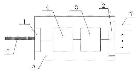
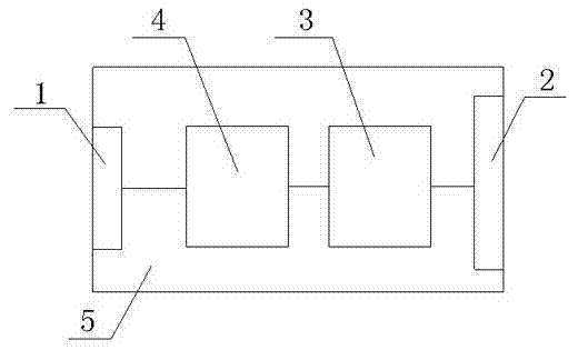
[0011] figure 1 An optical fiber splitting box is shown, which includes an optical fiber splitting box body 5, and the fiber optic cable splitting box body 5 is sequentially connected with a distribution cable fixing device 1, an optical fiber fusion splicing device 4, and an optical fiber connection distribution unit through optical cables from left to right. Device 3 , the incoming optical cable fixing device 2 , the distribution optical cable fixing device 1 and the incoming optical cable fixing device 2 are respectively arranged on the left side wall and the right side wall of the optical fiber splitting box 1 .

[0012] figure 2 After the distribution optical cable 6 shown enters the optical fiber distribution box, it is fixed by the distribution optical cable fixing device 1, and the distribution optical cable 6 is fixed on the optical fiber distribution box 5, so as to prevent the distribution optical cable 6 from being broken due to tying etc. Or fall off; after the...


PUM


Abstract

The invention relates to an optical cable distribution box which comprises an optical cable distribution box body. The optical cable distribution box is characterized in that: an optical distribution cable fixing device, a optical fiber welding apparatus, an optical fiber connection distribution apparatus and an introduction cable fixing apparatus are successively connected from left to right and are arranged in the optical cable distribution box; the optical distribution cable fixing device and the introduction cable fixing apparatus are respectively arranged on a left sidewall and a right sidewall of the optical cable distribution box. The structure can be used for a wiring and distribution device of a fiber loop terminal. Welding, the terminal, the wiring and the distribution functions of the optical fiber can be provided. One optical fiber is introduced into one home of a user. The wiring in the optical cable distribution box is clear. An on-site construction efficiency can be guaranteed.

Description

technical field [0001] The invention relates to an optical fiber distribution box applied in the field of optical communication. Background technique [0002] With the mature application of passive optical fiber network technology, the rapid development of new services including IP video and cloud computing, and the progress of society, people's requirements for high-bandwidth services such as high-definition interactive network TV and video surveillance continue to grow. The box has developed into a commonly used indoor and outdoor optical node product in the network. The function of the fiber optic cable splitter box is to connect the distribution fiber optic cable to the home butterfly cable through an optical splitter, but the traditional fiber optic cable splitter box Generally, it is simply refitted from the optical cable terminal box. Therefore, since the cable inlet hole on the optical cable distribution box is only provided with a closed hole on the box wall, the fi...

Claims


Application Information

Patent Timeline
Patent Type & Authority Applications(China)
IPC IPC(8): G02B6/44
Inventor 陈磊
Owner SUZHOU NEW DACHENG TECH DEV
Why Eureka
Try Eureka