Dielectric Waveguide Slot Antenna

A slot antenna and dielectric technology, which is applied to leaky waveguide antennas, slot antennas, circuits, etc., can solve the problems such as hindering the popularization of waveguide type circularly polarized wave antennas, difficulty in application of light weight, thinning and low price, etc.

Active Publication Date: 2015-10-14
MURATA MFG CO LTD
View PDF6 Cites 92 Cited by
  • Summary
  • Abstract
  • Description
  • Claims
  • Application Information

AI Technical Summary

Problems solved by technology

[0009] The above-mentioned method leads to problems such as an increase in the size of the antenna system with the formation of power supply circuits such as branch circuits, an increase in mass production costs due to the complexity of the structure, and an increase in the size of the waveguide for antenna arrays. Therefore, it is difficult to apply to such as mobile Lightweight, thin and low-cost applications such as body communication terminals are required, which hinders the popularization of waveguide-type circularly polarized wave antennas

Method used


Image

  • Dielectric Waveguide Slot Antenna
  • Dielectric Waveguide Slot Antenna
  • Dielectric Waveguide Slot Antenna

Examples


Embodiment Construction

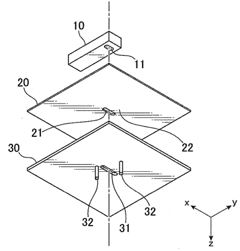
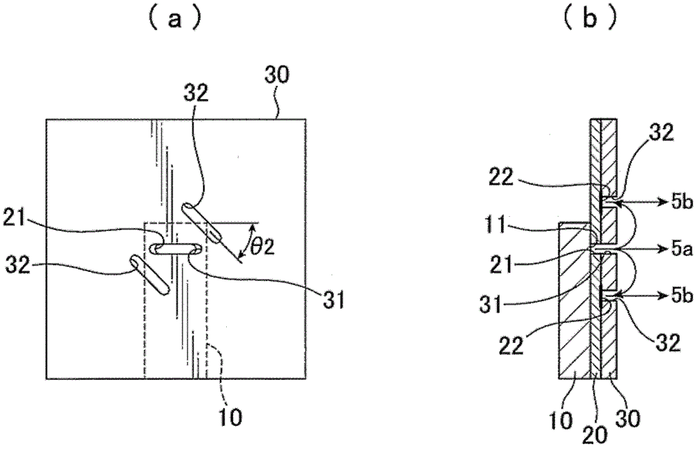
[0033] Next, the dielectric waveguide slot antenna of the present invention will be described using an embodiment. figure 1 It is an exploded perspective view of the dielectric waveguide slot antenna of the present invention. Such as figure 1 As shown, 10 is a dielectric waveguide, 20 is a printed substrate, and 30 is a conductor plate.

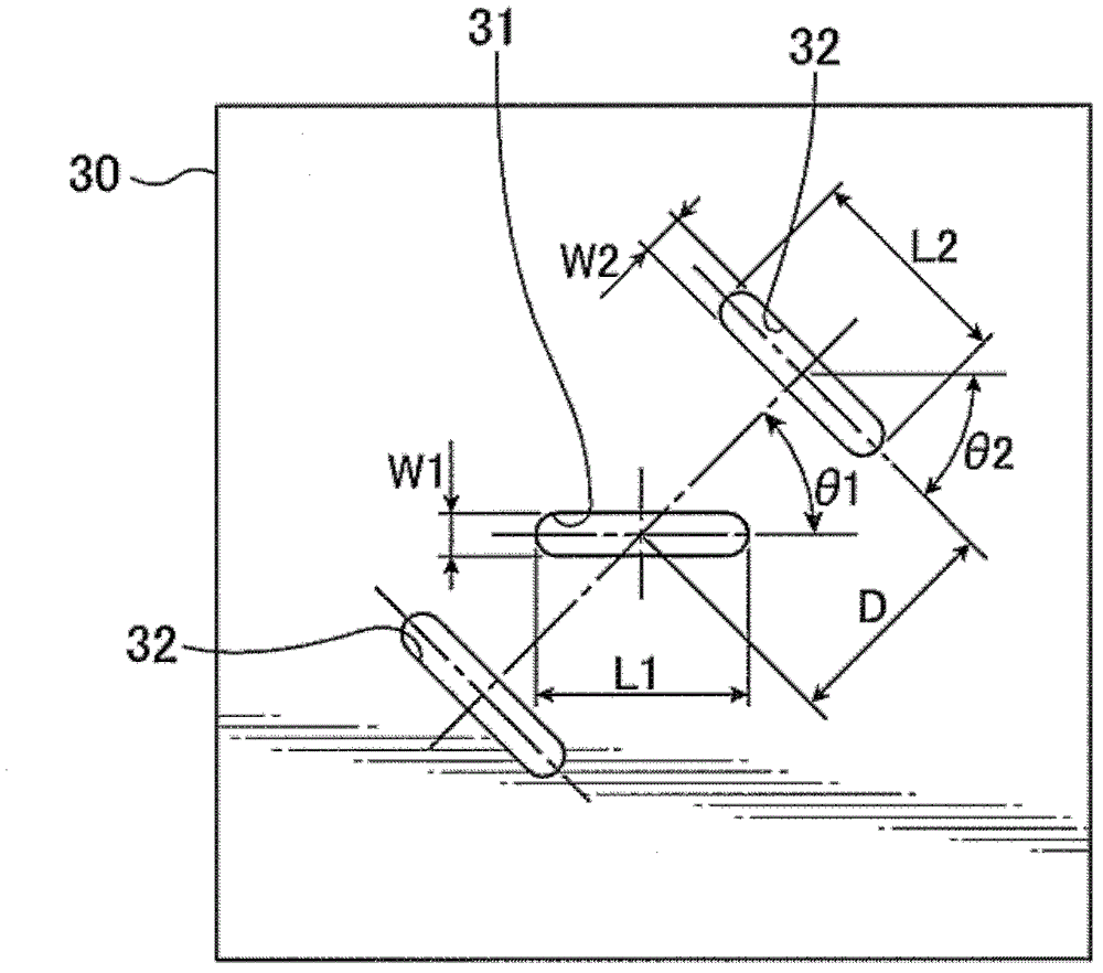
[0034] A dielectric waveguide 10 in which a conductive film is formed on the surface of a dielectric and has a slit 11 in which the dielectric is exposed in a part of the conductive film is mounted on a printed circuit board in which a through hole 21 having substantially the same shape as the slit 11 is formed at a position facing the slit 11. on the substrate 20, and is bonded with the conductor plate 30, the conductor plate 30 has a first through hole 31 having substantially the same shape as the above-mentioned through hole 21 at a position opposite to the above-mentioned through-hole 21, and a first through-hole 31 near the above-ment...


PUM


Abstract

A dielectric waveguide slot antenna which is capable of radiating a circularly-polarized wave comprises: a dielectric waveguide having a slot through which a dielectric is exposed in a part of an electrically conductive film formed on a surface of the dielectric waveguide; a printed circuit board having a via hole opposed to the slot with the same shape as that of the slot; and a conductor plate having a first through-hole opposed to and having approximately the same shape as the via hole, and a pair of second through-holes in a vicinity of the first through-hole. The dielectric waveguide, the printed circuit board and the conductor plate are joined together with aligning the slot, the via hole and the first through-hole with each other. The printed circuit board has a conductor layer formed in positions facing to the second through-holes, and the second through-holes are arranged point-symmetrically with each other.

Description

technical field [0001] The present invention relates to a slot antenna powered by a dielectric waveguide in the microwave and millimeter wave bands, and more particularly to a dielectric waveguide slot antenna capable of emitting circularly polarized waves with a simple structure. Background technique [0002] A dielectric waveguide slot antenna has been proposed as an antenna using a dielectric waveguide which is one type of transmission line. Dielectric waveguide slot antennas are suitable for microwave and millimeter wave bands. Figure 9 An exploded perspective view showing a conventional dielectric waveguide slot antenna. [0003] Such as Figure 9 As shown, the conventional dielectric waveguide slot antenna includes a slot 110 in which the dielectric is exposed on the bottom surface of the dielectric waveguide 100, and is mounted on a printed circuit board in which a through hole 210 having substantially the same shape as the slot 110 is formed at a position facing the...

Claims


Application Information

Patent Timeline
Patent Type & Authority Patents(China)
IPC IPC(8): H01Q13/22
CPCH01Q13/10
Inventor 谷田部主一伊藤一洋
Owner MURATA MFG CO LTD
Why Eureka
Try Eureka