Cable connector component

A cable connector and component technology, applied in the direction of connection, connecting device parts, fixed connection, etc., can solve the problem of high overall height of cable connector components, achieve structure miniaturization, prevent electromagnetic interference, and reduce overall height Effect

Active Publication Date: 2012-04-11
FOXCONN (KUNSHAN) COMPUTER CONNECTOR CO LTD +1
View PDF4 Cites 8 Cited by
  • Summary
  • Abstract
  • Description
  • Claims
  • Application Information

AI Technical Summary

Problems solved by technology

[0002] Most cable connector assemblies include an insulating body, a number of conductive terminals assembled in the insulating body, wires electrically connected to these conductive terminals, and a metal shell covering the periphery of the insulating body. The cable connector assembly It also includes a shell assembled on the periphery of the metal shell. In the existing cable connector assembly, the metal shell is usually completely covered on the periphery of the insulating body and then the outer shell is covered. It is arranged on the outside of the metal shell. This method will lead to a high overall height of the entire cable connector assembly, which cannot meet the requirements of today's society for the miniaturization of the structure of the cable connector assembly.

Method used


Image

  • Cable connector component
  • Cable connector component
  • Cable connector component

Examples


Embodiment Construction

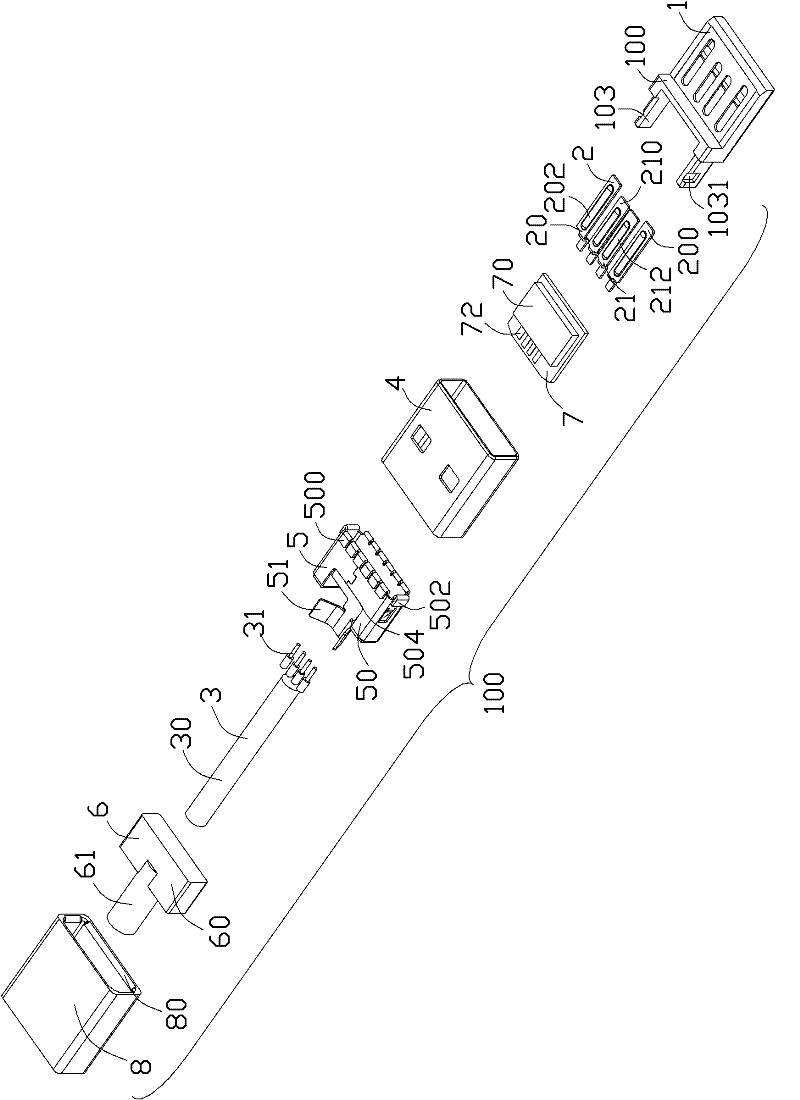
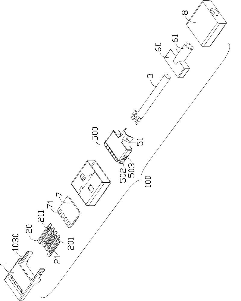
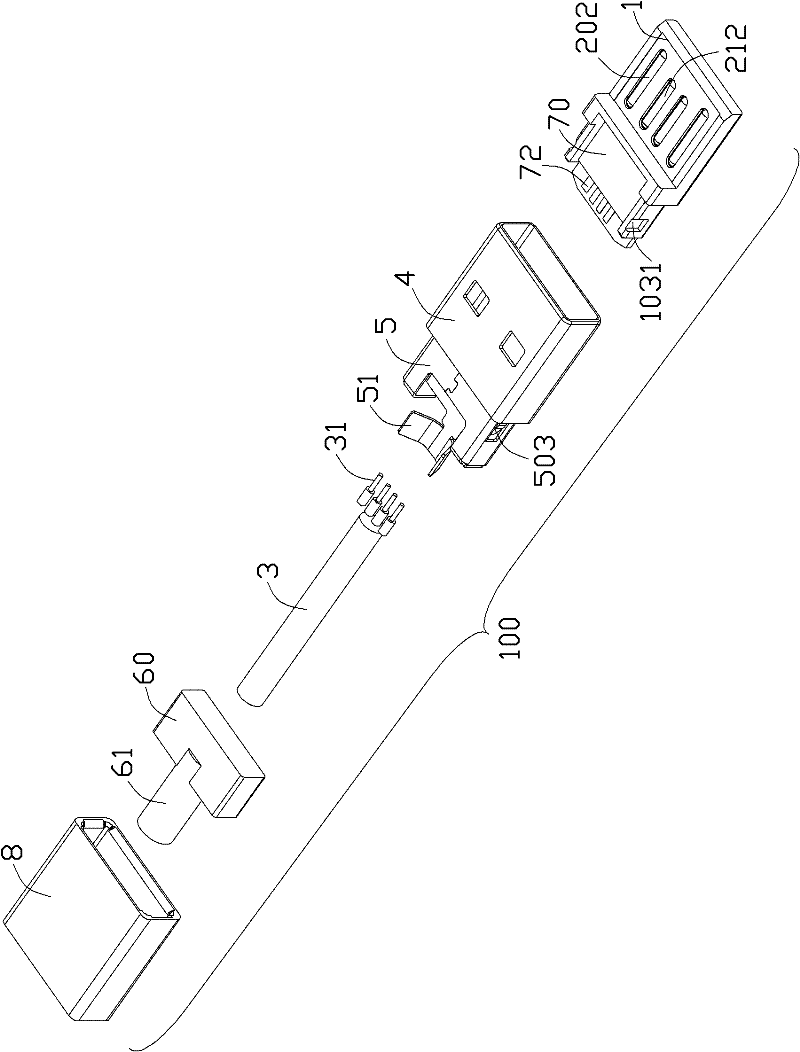
[0013] The cable connector assembly 100 of the present invention includes a conductive terminal 2, an insulating body 1 formed on the periphery of the conductive terminal 2, a cable 3 electrically connected to the conductive terminal 2, and a metal covering the outer periphery of the insulating body 1. The outer shell 4 and the metal inner shell 5 arranged behind the metal outer shell 4 .

[0014] Please refer to Figure 1 to Figure 2 As shown, the insulator body 1 is roughly in the shape of a cuboid, and the insulator body 1 includes a flat plate portion 100 located in front of it and shielded inside the metal shell 4, and left and right sides from the rear surface of the flat plate portion 100. The cantilever 103 formed by extending laterally and rearwardly is shielded inside the metal inner shell 5 . From the inner side wall of the cantilever 103 near the lower surface of the cantilever 103 are respectively formed with slide grooves 1030 extending in the front and rear dir...


PUM


Abstract

The invention relates to a cable connector component, comprising a conducting terminal, an insulating body, a cable and a metal outer shell, wherein the insulating body is arranged at the periphery of the conducting terminal; the cable is electrically connected with the conducting terminal; the metal outer shell shields the periphery of the insulating body; the cable connector component also comprises a metal inner shell which is arranged behind the metal outer shell; and the outer surface of the front end of the metal inner shell is protruded to form a plurality of boss parts combined with the internal surface of the metal outer shell.

Description

【Technical field】 [0001] The invention relates to a cable connector assembly, in particular to a cable connector assembly with a miniaturized structure. 【Background technique】 [0002] Most cable connector assemblies include an insulating body, a number of conductive terminals assembled in the insulating body, wires electrically connected to these conductive terminals, and a metal shell covering the periphery of the insulating body. The cable connector assembly It also includes a shell assembled on the periphery of the metal shell. In the existing cable connector assembly, the metal shell is usually completely covered on the periphery of the insulating body and then the outer shell is covered. It is arranged on the outside of the metal shell, and this method will lead to a high overall height of the entire cable connector assembly, which cannot meet the requirements of today's society for the structure miniaturization of the cable connector assembly. [0003] Therefore, it ...

Claims


Application Information

Patent Timeline
Patent Type & Authority Applications(China)
IPC IPC(8): H01R13/648H01R13/46
CPCH01R13/6581H01R12/57H01R13/6658H01R13/26
Inventor 吴荣发
Owner FOXCONN (KUNSHAN) COMPUTER CONNECTOR CO LTD
Why Eureka
Try Eureka