
Ultrasonic transducer

An ultrasonic transducer and ultrasonic technology, applied in ultrasonic therapy, treatment and other directions, can solve the problems of difficult to achieve the traditional acupuncture treatment effect, damaged tissue, and the stimulation area cannot be covered at the same time.

Active Publication Date: 2012-04-18
RONGHAI SUPERSONIC MEDICINE EN
View PDF3 Cites 13 Cited by
  • Summary
  • Abstract
  • Description
  • Claims
  • Application Information

AI Technical Summary

Problems solved by technology

[0005] Acupuncture points, as the acupuncture points during acupuncture, are not just a single point but an area with a certain depth (the position of each acupoint on the human body surface varies in depth) and breadth. Accurate stimulation must be done to the entire area. Although the existing focus transducers require a targeting effect in the tissue, due to the small area of ​​the ultrasonic wave (the stimulation area to the tissue is only a small area centered on the focus). ellipsoid area), the stimulation area generated in the tissue cannot cover the area required by acupuncture and moxibustion at the same time, so it cannot completely simulate the acupuncture techniques in traditional acupuncture and moxibustion, making it difficult to achieve the therapeutic effect of traditional acupuncture and moxibustion
And this type of focusing transducer has the possibility of damaging tissue due to the high energy converged at the focal point

Method used


Image

  • Ultrasonic transducer
  • Ultrasonic transducer
  • Ultrasonic transducer

Examples


Embodiment 1

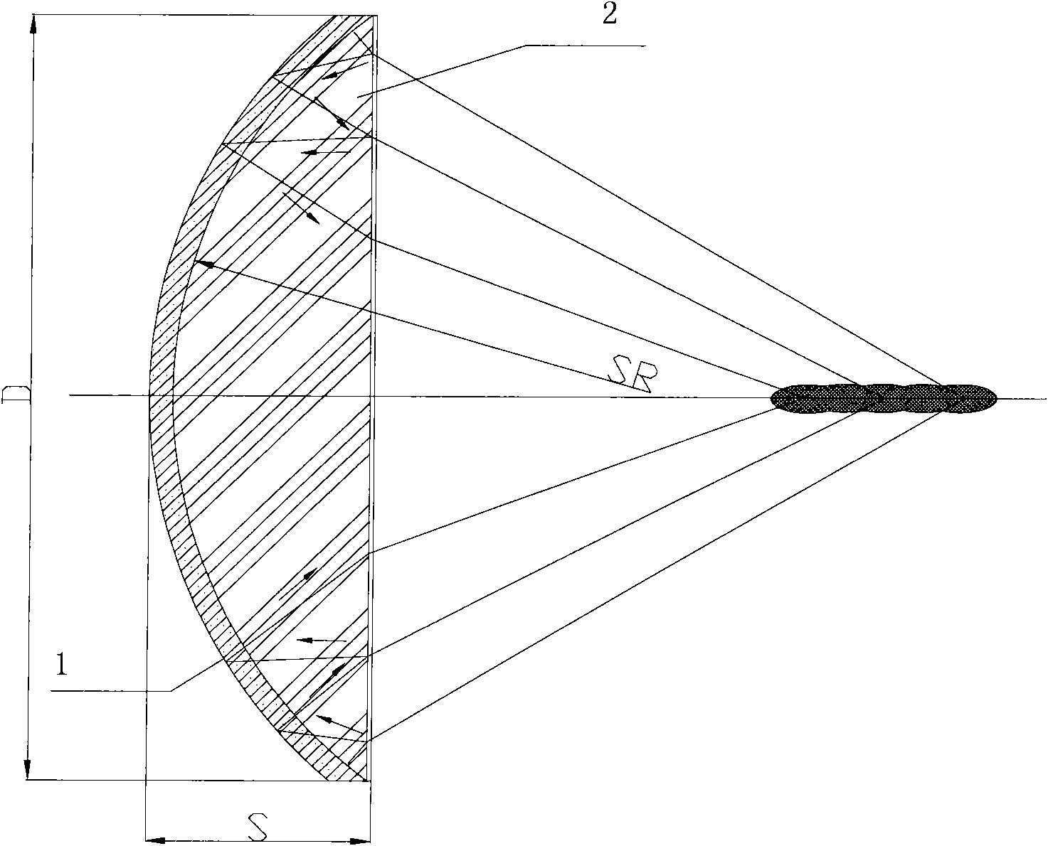
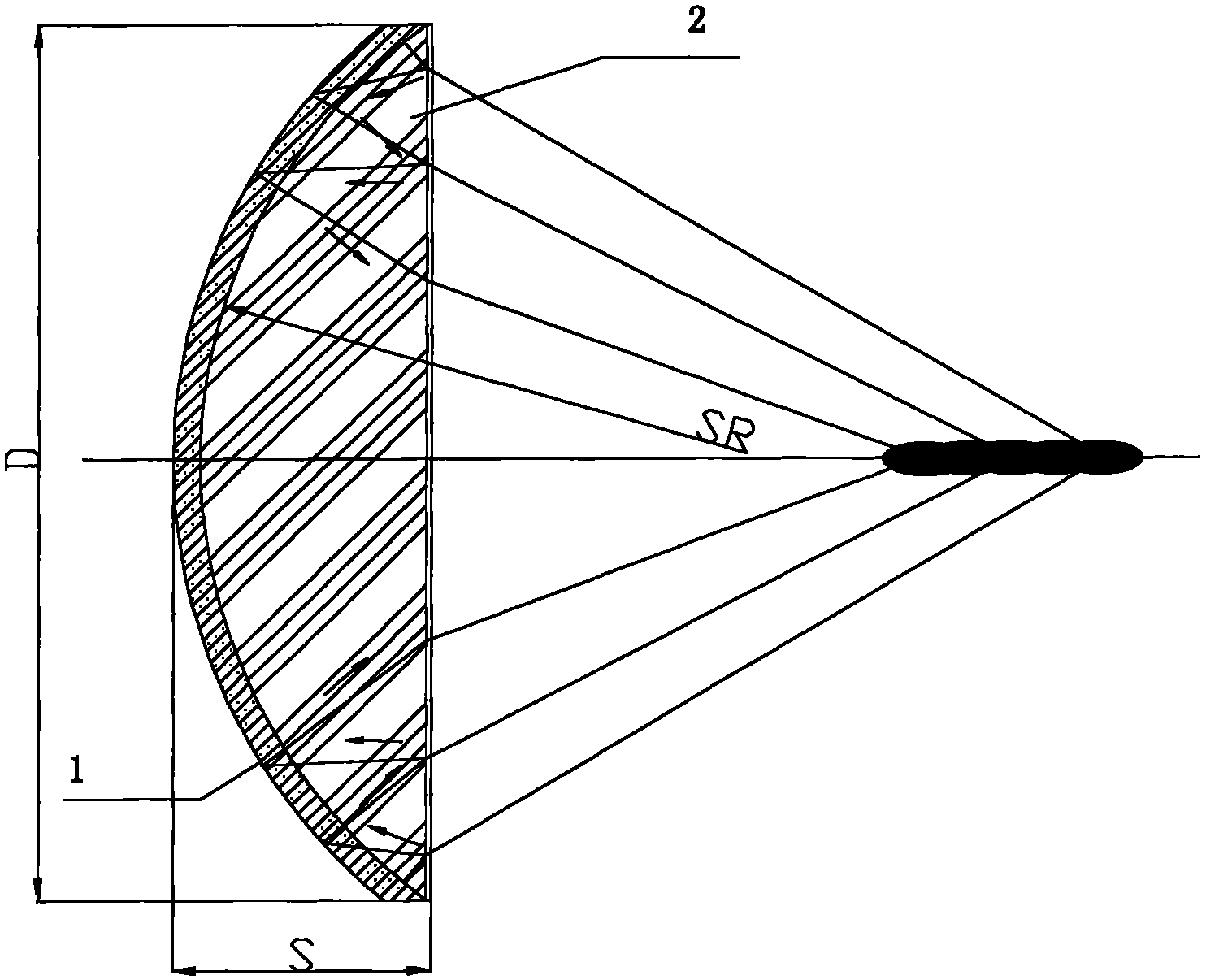
[0033] The ultrasonic transducer of the present invention includes an ultrasonic emitting unit, and the ultrasonic emitting unit includes a focused wave source 1 and an ultrasonic conduction unit 2 .

[0034] The ultrasonic conduction unit 2 is arranged on the ultrasonic transmission path of the ultrasonic waves emitted by the focused wave source 1 , and the ultrasonic waves emitted by the focused wave source 1 are collected on the acoustic axis of the ultrasonic wave after passing through the ultrasonic conduction unit 2 and extend along the direction of the ultrasonic sound axis.

[0035] Such as figure 1 As shown, in this embodiment, the focused wave source 1 adopts a spherical shell-shaped wave source with ultrasonic reflection function, and the ultrasonic conduction unit 2 is a spherical crown, which is placed inside the spherical shell-shaped wave source, and the spherical shell-shaped The wave source fits snugly. The shape of the contact surface of the ultrasonic transmi...

Embodiment 2

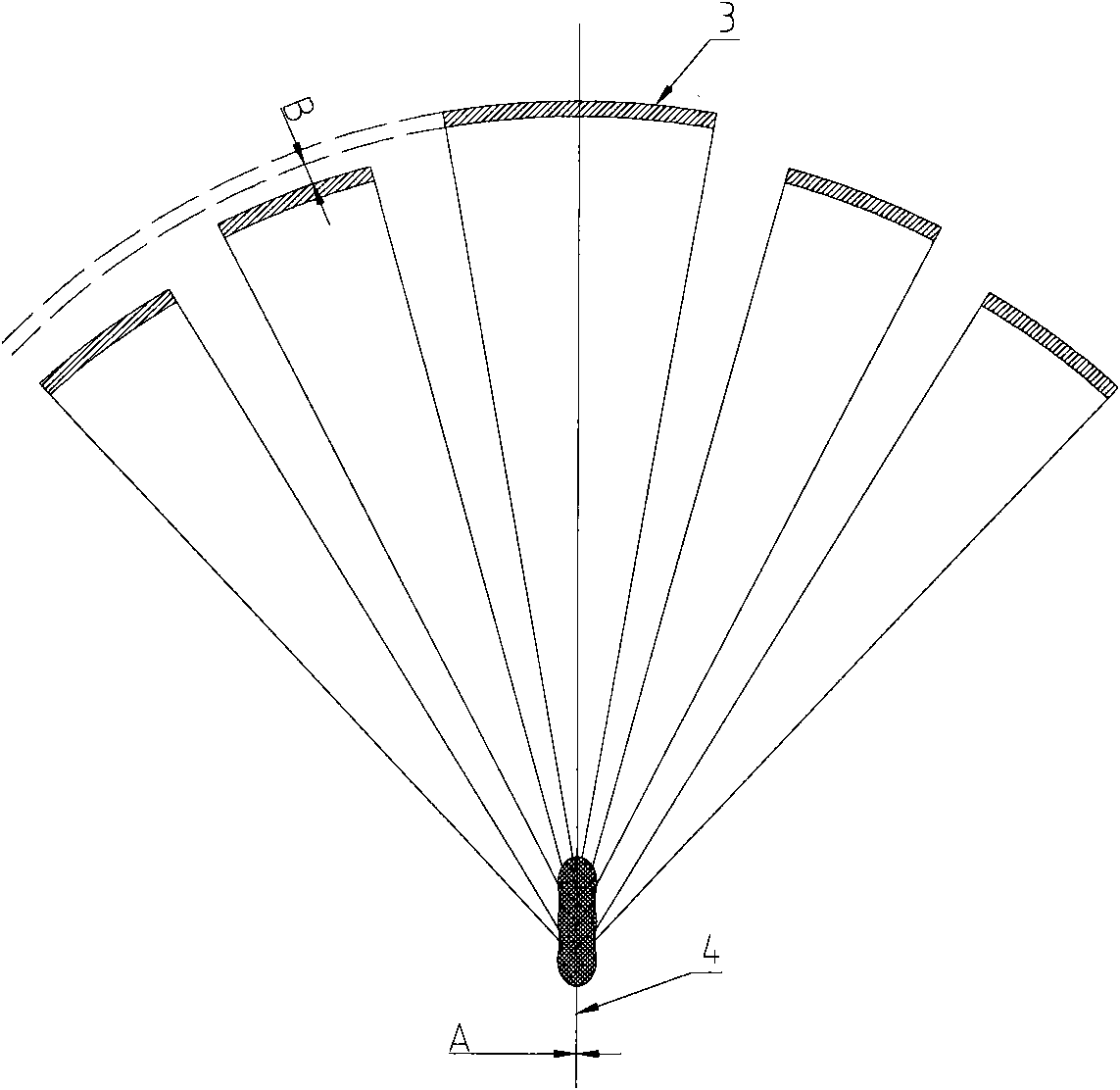
[0045] Such as figure 2 As shown, in this embodiment, the ultrasonic transmitting unit includes two or more focused wave sources 3, and the two or more focused wave sources 3 are composed of a spherical shell formed by one or more parallel planes perpendicular to the ultrasonic acoustic axis 4. The spherical wave source is divided into a spherical crown and two adjacent rings (of course, the spherical shell-shaped wave source can also be divided into a spherical crown and multiple rings according to the needs), and then a spherical crown formed after the division and After the two rings are pulled apart along the direction of the ultrasonic acoustic axis 4, they are placed at a certain distance from each other to form a spherical cap or a ring formed as a focused wave source 3.

[0046] Of course, the plurality of focused wave sources 3 in the ultrasonic transmitting unit may not include the spherical caps formed by the above divisions, but two or more circular rings formed b...


PUM

PropertyMeasurementUnit
Caliberaaaaaaaaaa
Center thicknessaaaaaaaaaa
Lengthaaaaaaaaaa

Abstract

The invention discloses an ultrasonic transducer, which comprises an ultrasonic emission unit for emitting focusing ultrasonic, wherein the focus domain formed by the ultrasonic emitted by the ultrasonic emitting unit is of a strip shape and extends along the axial line direction of the ultrasonic. According to the invention, a long-focus-domain ultrasonic transducer is provided for the existing ultrasonic acupuncture and moxibustion equipment, so that the ultrasonic acupuncture and moxibustion equipment can completely stimulate acupuncture manipulation of traditional acupuncture.

Description

technical field [0001] The invention belongs to the technical field of ultrasonic therapy, and in particular relates to an ultrasonic transducer. Background technique [0002] Ultrasound is increasingly used in therapy and diagnosis due to its ability to penetrate tissue while producing no ionizing radiation to tissue. In ultrasonic therapy and ultrasonic diagnosis, the commonly used ultrasonic transducers are planar ultrasonic transducers and focused ultrasonic transducers. [0003] Focused ultrasound transducers can form non-invasive targeting effects in tissues, and in recent years, the use of focused ultrasound transducers has become more and more common. At present, there are many kinds of focused ultrasonic transducers on the market, such as lens transducers, spherical shell transducers, Fresnel zone plate transducers, phased array focusing transducers, and parabolic reflective transducers. The characteristic of these focusing transducers is that the ultrasonic wave ...

Claims


Application Information

Patent Timeline
IPC IPC(8): A61N7/00
Inventor 王华曾德平王智彪黄光华谭智彬
Owner RONGHAI SUPERSONIC MEDICINE EN
Learn More