Automobile air conditioner

A technology for automotive air conditioners and cabins, applied in vehicle components, air handling equipment, heating/cooling equipment, etc., to solve problems such as reducing air ventilation resistance and inability to solve

Inactive Publication Date: 2012-04-18
宋小民
View PDF7 Cites 3 Cited by
  • Summary
  • Abstract
  • Description
  • Claims
  • Application Information

AI Technical Summary

Problems solved by technology

The air duct shape of the automobile air conditioner air supply duct adopts a streamlined structure, which makes the air flow more smoothly inside the air duct. out of car problem

Method used


Image

  • Automobile air conditioner
  • Automobile air conditioner
  • Automobile air conditioner

Examples


Embodiment 1

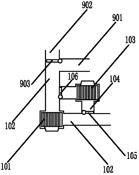
[0062] Such as figure 1 As shown, the first embodiment of the automobile air conditioner of the present invention includes an external air port 901 communicating with the air outside the vehicle cabin, an internal circulation air outlet 902 communicating with the air inside the vehicle cabin, and a switch for switching between the external air outlet 901 and the internal circulation air outlet 902 The reversing valve 903 and the two-way ventilation device located in the car air conditioner.

[0063] Among them, the two-way ventilation device includes: a one-way intake fan 101 and a main pipe 102 connected to the one-way intake fan 101; a one-way exhaust fan 103 and a bypass pipe 104 connected to both ends of the one-way exhaust fan 103; Switching mechanism (two reversing valves 105, 106). Wherein, one end of the main road pipe 102 is connected to the external tuyere 101. The reversing valves 105 and 106 are located at the connecting ends of the main pipeline 102 and the bypass p...

Embodiment 2

[0067] Such as Figure 4 As shown, the other parts of this embodiment are the same as the embodiment 1, the difference is that the two-way ventilation device includes: a one-way fan 201, main pipeline (intake section 202, outlet section 203), bypass pipeline (inlet section) Air pipe 204, air outlet pipe 205), switching mechanism (reversing valves 206, 207, 208). Among them, the reversing valve 206 is located at the connecting end of the air inlet pipe 204 and the outlet section 203 of the main pipeline, the reversing valve 207 is located at the connecting end of the outlet pipe 205 and the outlet section 203 of the main pipeline, and the reversing valve 208 is located at the outlet pipe 205 and The connecting end of the air inlet section 202 of the main pipeline. In addition, the connecting end of the air inlet pipe 204 and the air inlet section 202 of the main pipeline is closer to the one-way fan 201 than the connecting end of the air outlet pipe 205 and the air inlet section...

Embodiment 3

[0071] Such as Figure 7 As shown, the other parts of this embodiment are the same as the embodiment 1, the difference is that the two-way ventilation device includes: a one-way fan 301, main pipeline (intake section 302, outlet section 303), bypass pipeline (inlet Air pipe 304, air outlet pipe 305), switching mechanism (ball valves 306, 307). One end of the air inlet pipe 304 and the air outlet pipe 305 is connected to the same position of the air inlet section 302 of the main pipe, and the connection position is provided with a ball valve 307; the other end of the air inlet pipe 304 and the air outlet pipe 305 is connected to the air outlet section 303 of the main pipe A ball valve 306 is provided in the connection position at the same position.

[0072] Figure 8 Shown is a schematic diagram of the air intake state of this embodiment. At this time, the one-way fan 301 is activated, and the ball valves 306 and 307 make the main road pipeline unblocked, so that the air outside t...


PUM


Abstract

The invention discloses an automobile air conditioner with air suction/exhaustion functions. The automobile air conditioner comprises an internal circulating air hole for circulating gas inside a carriage and one or more external air holes for the gas exchange between the inside of the carriage and the outside of the carriage, wherein the automobile air conditioner comprises a two-way ventilation device; the two-way ventilation device comprises a blower, and a gas pipeline and a switching mechanism which are connected with the blower; the blower can provide one-way or two-way gas flow; the gas pipeline is communicated with the external air holes; and the switching mechanism switches the flowing path or the flowing direction of gas inside the gas pipeline, so that air in the outside is sucked into the carriage or air in the carriage is exhausted to the outside, or air remained in an air-conditioning pipeline is directly exhausted outside the carriage without being circulated in the carriage. Through arranging the two-way ventilation device, the automobile air conditioner disclosed by the invention has the air internal circulating function and the air suction function of the existing automobile air conditioner, moreover, has the air exhaustion function, namely, the blower exhausts the air inside the carriage and exhausts the air inside the air-conditioning pipeline outside the carriage without being circulated in the carriage.

Description

Technical field [0001] The invention relates to an automobile air conditioner. Background technique [0002] The automobile air conditioning system is a device that realizes cooling, heating, ventilation and air purification of the air in the vehicle compartment. The air circulation through the car air conditioner can be divided into the internal circulation inside the car and the gas exchange inside and outside the car. The internal circulation means that the wind blown by the blower only circulates inside the car without the participation of external air. Its advantages are fuel saving and fast cooling (heating), but its disadvantage is that it is not conducive to the renewal of the air in the car; the existing technology of gas exchange is It means that the blower sucks air from the outside of the car and blows it into the car. Its advantage is to maintain the freshness of the air in the car, but its disadvantage is that it consumes fuel and is slow in cooling (heating). [00...

Claims


Application Information

Patent Timeline
Patent Type & Authority Applications(China)
IPC IPC(8): B60H1/00B60H1/26
Inventor 宋小民
Owner 宋小民
Why Eureka
Try Eureka