Electric brake boosting device

A brake booster device, an electric technology, is applied in the field of brake booster devices of automobile service brake systems, and can solve problems such as application difficulties and the like

Inactive Publication Date: 2012-04-18
ZHEJIANG NORMAL UNIVERSITY
View PDF4 Cites 17 Cited by
  • Summary
  • Abstract
  • Description
  • Claims
  • Application Information

AI Technical Summary

Problems solved by technology

Due to the defects of the traditional vacuum servo type and pneumatic servo type servo brake booster, it is difficult to apply them on these two types of vehicles. Only by developing a new type of brake booster can it meet the requirements.

Method used


Image

  • Electric brake boosting device
  • Electric brake boosting device
  • Electric brake boosting device

Examples


Embodiment Construction

[0024] The present invention will be further described below in conjunction with the accompanying drawings and specific embodiments.

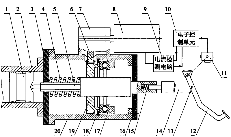
[0025] like figure 1 As shown, an electric brake booster is composed of a mechanical device and an electronic control system, wherein the mechanical device mainly includes a booster body, a threaded transmission mechanism and a reduction mechanism 7, and the booster body is composed of a booster housing 20, a booster The cylindrical cavity surrounded by the front end cover 3 of the booster and the rear end cover 16 of the booster has a built-in booster screw 5 processed with external threads, and the booster screw 5 cooperates with a booster gear 19 processed with internal threads to form a threaded transmission mechanism. The input of the reduction mechanism 7 comes from the stepping motor 8 of the electronic control system, and the output gear 6 of the reduction mechanism drives the power assist gear 19 through tooth meshing. The electronic ...


PUM


Abstract

The invention provides an electric brake boosting device, and relates to an automobile running brake system. In the device, the force of a brake pedal is transmitted to a piston of a brake main cylinder through a pedal push rod, a push rod spring and a boosting screw rod, the brake pedal is provided with a brake pedal position sensor to sense the operating intension of a driver, an electronic control unit determines the quick degree of providing boost on the basis, calculates the boosting travel according to the preset compression of the push rod spring between the pedal push rod and the boosting screw rod, and controls a step motor to drive a boosting gear through a reducing gear, so that a thread mechanism drives the boosting screw rod to linearly move to realize boosting brake. When the brake pedal stops, the motor does not rotate, and the device maintains the braking force by means of the self-locking function of threads. When the brake pedal is released, the motor rotates reversely, and the boosting screw rod returns to the original position under the action of the reducing gear and the thread mechanism. The foot feel during brake is ensured by keeping the compression of the push rod spring, the boosting effect is obvious, and the structure is simple.

Description

technical field [0001] The invention relates to an automobile electronic control product, in particular to a brake booster device of an automobile service brake system, and is especially suitable for use in pure electric automobiles and hybrid electric automobiles. Background technique [0002] At present, most of the service brake systems used in cars are servo brake boosters. The servo brake system is formed by adding a power servo device on the basis of the hydraulic brake system. When the driver takes a brake operation, he applies the brake force on the brake pedal and transmits the brake force to the brake master cylinder through the rod system. On the piston, the servo device also works at the same time, and supplies most of the braking energy, which can reduce the driver's operating intensity. If the servo fails, the original hydraulic brake can still function, and the driver needs a larger braking force to meet the needs of the vehicle brake. There are mainly two t...

Claims


Application Information

Patent Timeline
Patent Type & Authority Applications(China)
IPC IPC(8): B60T13/74
Inventor 赵迎生
Owner ZHEJIANG NORMAL UNIVERSITY
Why Eureka
Try Eureka