

Compression garbage truck with top-mounted pushing mechanisms
A technology for pushing mechanisms and garbage trucks, which is applied in the direction of garbage bins, garbage collection, and garbage containers. It can solve problems such as insufficient garbage compression force, insufficient garbage compression force, and surface pollution on the upper part of the garbage box, so as to ensure filling efficiency and guarantee Firmness, Possibility-Reducing Effects
- Summary
- Abstract
- Description
- Claims
- Application Information
AI Technical Summary
Problems solved by technology
Method used
Image

Examples
Embodiment 1
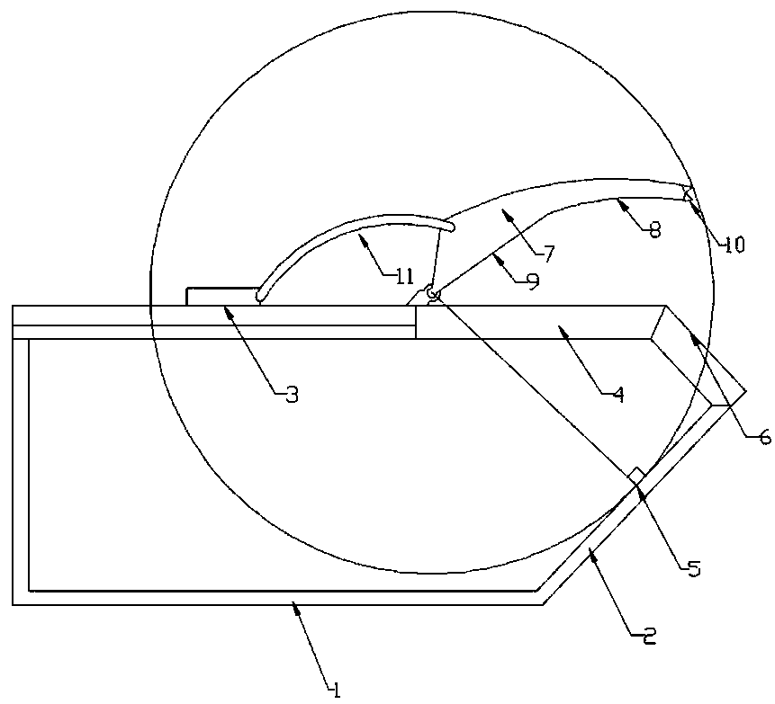
[0028] Such as figure 1 As shown, it is a compressed garbage truck with an improved structure, which mainly includes the body of the garbage box. A garbage introduction surface arranged at an obtuse angle with the bottom wall of the garbage box is set at one end of the garbage box body. A garbage inlet opening is set on the top wall of the garbage bin, and a turning opening arranged at right angles to the garbage inlet surface is arranged between the garbage inlet opening and the garbage inlet surface. A garbage compression plate is also rotated and connected on the top outer wall of the garbage bin, and the garbage can The inner side of the compression plate includes a horizontal surface part and an arc surface part. The horizontal surface part is rotationally connected with the top outer wall of the dustbin, and the end of the arc surface part is connected with a sealing part made of rubber strips. At the same time, the waste compression plate A push mechanism composed of te...
Embodiment 2
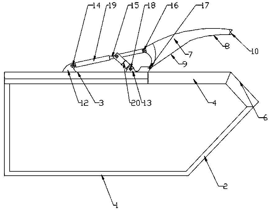
[0030] Such as figure 2 , Figure 4 , Figure 5 As shown, the present invention adopts a relatively simple and light-weight link mechanism to drive the garbage compression plate; it mainly includes the body of the garbage box, and an obtuse angle with the bottom wall of the garbage box is set at one end of the garbage box body. The garbage introduction surface is arranged. A garbage introduction opening is set on the top wall of the garbage bin body. A turning opening arranged at right angles to the garbage introduction surface is arranged between the garbage introduction opening and the garbage introduction surface. A garbage compression plate is also rotatably connected. The inner side of the garbage compression plate includes a horizontal part and an arc surface part. At the same time, a push mechanism composed of telescopic connectors is also rotatably connected to the garbage compression plate. The push mechanism is also rotatably connected to the top outer wall of the...
Embodiment 3
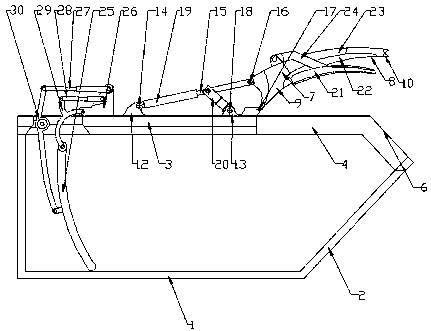
[0036] Such as image 3 As shown, a compressed garbage truck with an improved structure mainly includes a garbage bin body, and a garbage introduction surface arranged at an obtuse angle with the bottom wall of the garbage bin is provided at one end of the garbage bin body. A garbage introduction opening is set on the top wall, and a turning opening arranged at right angles to the garbage introduction surface is arranged between the garbage introduction opening and the garbage introduction surface. A garbage compression plate is also rotatably connected to the top outer wall of the garbage bin to compress the garbage. The inner side of the board includes a horizontal part and an arc-shaped part. The horizontal part is connected to the top outer wall of the garbage bin in rotation, and the end of the arc-shaped part is connected with a sealing part made of rubber strips. A push mechanism made of telescopic connectors is also rotatably connected, and the push mechanism is also r...
PUM
 Abstract
Description
Claims
Application Information