Polycarbonate (PC) composite bridge with corrugated steel webs and construction method for PC composite bridge

A technology of corrugated steel webs and corrugated steel plates, applied in bridges, bridge construction, erection/assembly of bridges, etc., can solve problems affecting the bending and torsional stiffness of double corrugated steel webs, and restrict the competitiveness of double corrugated steel web bridges , increasing costs and other issues, to achieve the effect of beautiful appearance, shortening the construction period, and improving local stress

Active Publication Date: 2012-04-18
SHENZHEN UNIV +1
View PDF8 Cites 40 Cited by
  • Summary
  • Abstract
  • Description
  • Claims
  • Application Information

AI Technical Summary

Problems solved by technology

[0005] 1. The two layers of corrugated steel plates of the double corrugated steel web are hollow, and the two layers of corrugated steel plates are separated from each other without forming a whole. This is not only not conducive to local stress, but also seriously affects the bending resistance and Torsional rigidity, and due to insufficient rigidity during construction, its own stability is poor, and more supports are needed to maintain the stability of double corrugated steel webs, which greatly restricts the competiti

Method used


Image

  • Polycarbonate (PC) composite bridge with corrugated steel webs and construction method for PC composite bridge
  • Polycarbonate (PC) composite bridge with corrugated steel webs and construction method for PC composite bridge
  • Polycarbonate (PC) composite bridge with corrugated steel webs and construction method for PC composite bridge

Examples


Embodiment Construction

[0041] The present invention will be further described below in conjunction with the accompanying drawings and specific embodiments.

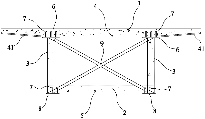
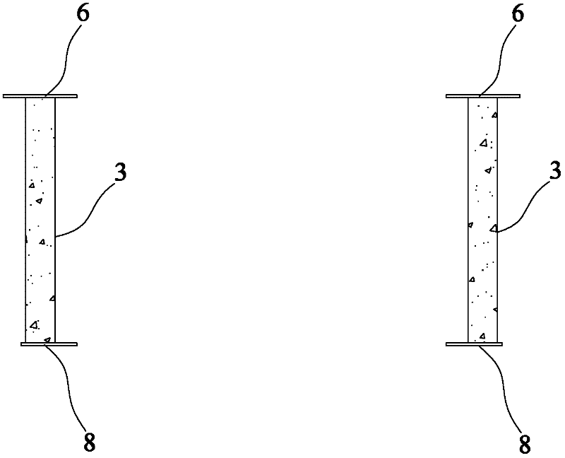
[0042] Please refer to figure 1 and figure 2 As shown, it shows a specific structure of a PC bridge with corrugated steel webs in the present invention, including a concrete roof 1, a concrete floor 2, and two double waveforms that are symmetrically distributed between the concrete roof 1 and the concrete floor 2 Steel web 3, the double corrugated steel web 3 can be erected or obliquely erected, wherein:

[0043] The bottom surface of the concrete roof 1 is equipped with an upper profiled steel plate 4 , and the bottom surface of the concrete bottom plate 2 is equipped with a lower profiled steel plate 5 .

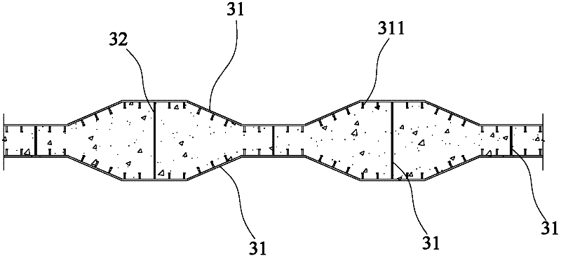
[0044]The double corrugated steel web 3 includes two layers of corrugated steel plates 31 and a plurality of connectors 32 connected between the two layers of corrugated steel plates 31, and the connectors 32 are connected between the tw...


PUM


Abstract

The invention discloses a polycarbonate (PC) composite bridge with corrugated steel webs and a construction method for the PC composite bridge. The PC composite bridge comprises a concrete top plate, a concrete bottom plate and two double-corrugated steel webs; the bottom surface of the concrete top plate and the concrete bottom plate are provided with upper and lower profiled steel sheets; each double-corrugated steel web comprises two layers of corrugated steel plates and a plurality of connecting pieces; concrete is filled between the two layers of corrugated steel plates; the connecting pieces are connected between the two layers of corrugated steel plates, so that the two corrugated steel plates work together and the aim of greatly improving bending rigidity and torsional rigidity is fulfilled; the upper ends of the double-corrugated steel webs are connected with steel top plates connected with the upper profiled steel plate; and the lower ends of the double-corrugated steel webs are connected with steel bottom plates connected with the lower profiled steel plate. The double-corrugated steel webs are integral, the bending rigidity and torsional rigidity are improved by more than 4 times, the stability is high during construction, and the application range of the bridge is widened; and the profiled steel plates are adopted, so that formwork supports for the concrete top plate and the concrete bottom plate are eliminated during construction, construction without formworks and with a few supports is realized, the cost is reduced and the construction period is shortened.

Description

[0001] Technical field [0002] The invention involves a bridge and its construction method, especially a wave -shaped steel abdomen combination PC bridge and its construction method. [0003] Background technique [0004] With the development of bridge construction technology, people have found that wave -shaped steel abdomen has stronger shear and crack resistance than concrete abdomen. Therefore, more and more bridges use waveform steel abdomen bridges.People use single -wave steel abdomen plates when building waveform steel abdomen bridges. At the present stage, some waveform steel abdomen bridges have used double -wave -shaped steel abdomen. For exampleA two -wave gastrointestinal steel box beam, the abdomen of the double -wave gastrointestinal steel box beam is a double -wave -shaped steel abdomen, with two -layer waveform steel plate, a double -wave steel abdomen plate and a single -wave -shaped steel abdomen with only one layer of wave -shaped steel plateCompared with the...

Claims


Application Information

Patent Timeline
IPC IPC(8): E01D2/00E01D21/00
Inventor 李勇陈宜言朱宏平刘念琴李海王先前董桔灿王远洋
Owner SHENZHEN UNIV
Why Eureka
Try Eureka