Shutter

A shutter and blade technology, applied in the field of shutters, can solve the problems of low installation efficiency, great installation difficulty, affecting the overall strength and aesthetics of shutters, etc., and achieve the effects of convenient installation and adjustment, saving production costs, and simple and reliable overall structure.

Active Publication Date: 2012-04-18
HUNAN GOLDWELL NEW MATERIALS TECH CO LTD
View PDF6 Cites 1 Cited by
  • Summary
  • Abstract
  • Description
  • Claims
  • Application Information

AI Technical Summary

Problems solved by technology

[0002] The shutters made of metal have high strength and good protection, especially the shutters made of zinc-coated steel plates on the surface have strong anti-rust and anti-corrosion capabilities, and the material cost is low and cheap. At present, they are gradually replacing aluminum alloy shutters on the market. However, the blades of the galvanized steel louvers with surface spraying are all stamped and bent, and it is inconvenient to set screw holes at both ends of the blades. Put the blade fixing pads in the fixing holes, and use the blade fixing pads to position the blades. When installing, insert one end of all the blades into the blade fixing pads of one frame one by one, and then connect each blade fixing pad of the other frame with the corresponding The other ends of the blades are aligned one by one. If there is a misalignment, the blades cannot be docked with the frame. The more blades, the more difficult it is to install and the lower the installation efficiency. In addition, the distance between the blades depends entirely on fasteners ( Usually it is a self-tapping screw) to control the fixed position of the blade fixing pad. Once fixed, the distance cannot be adjusted. If the fastener is removed and the blade is fixed after moving and adjusting, the frame will remain in its original position. Fastener mounting holes that affect the overall strength and aesthetics of the shutter

Method used


Image

  • Shutter
  • Shutter
  • Shutter

Examples


Embodiment Construction

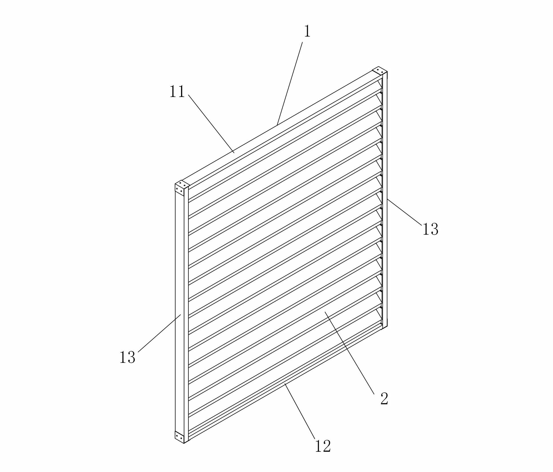
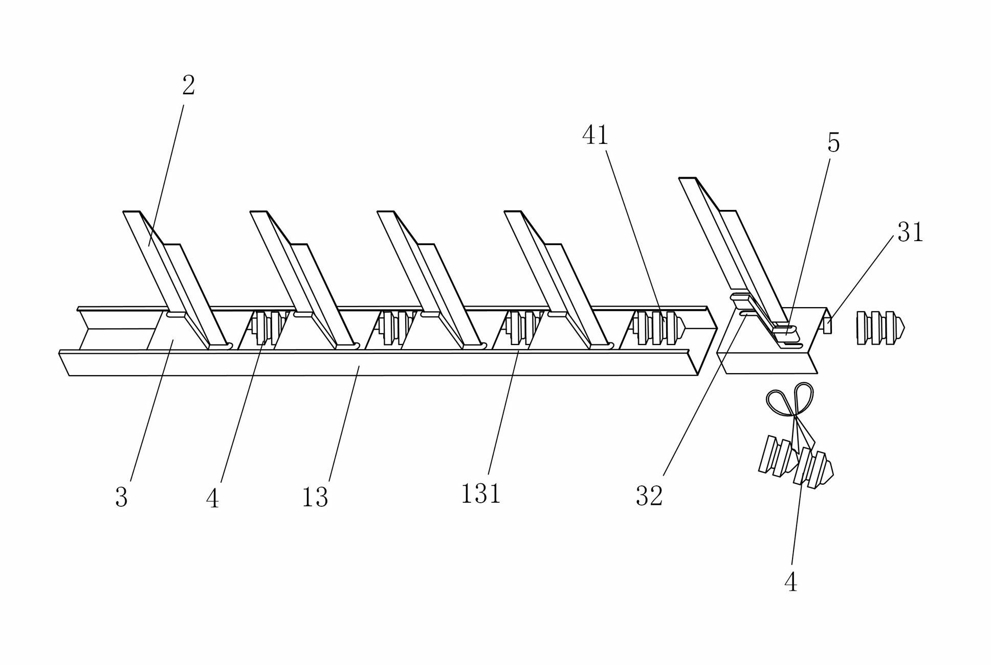
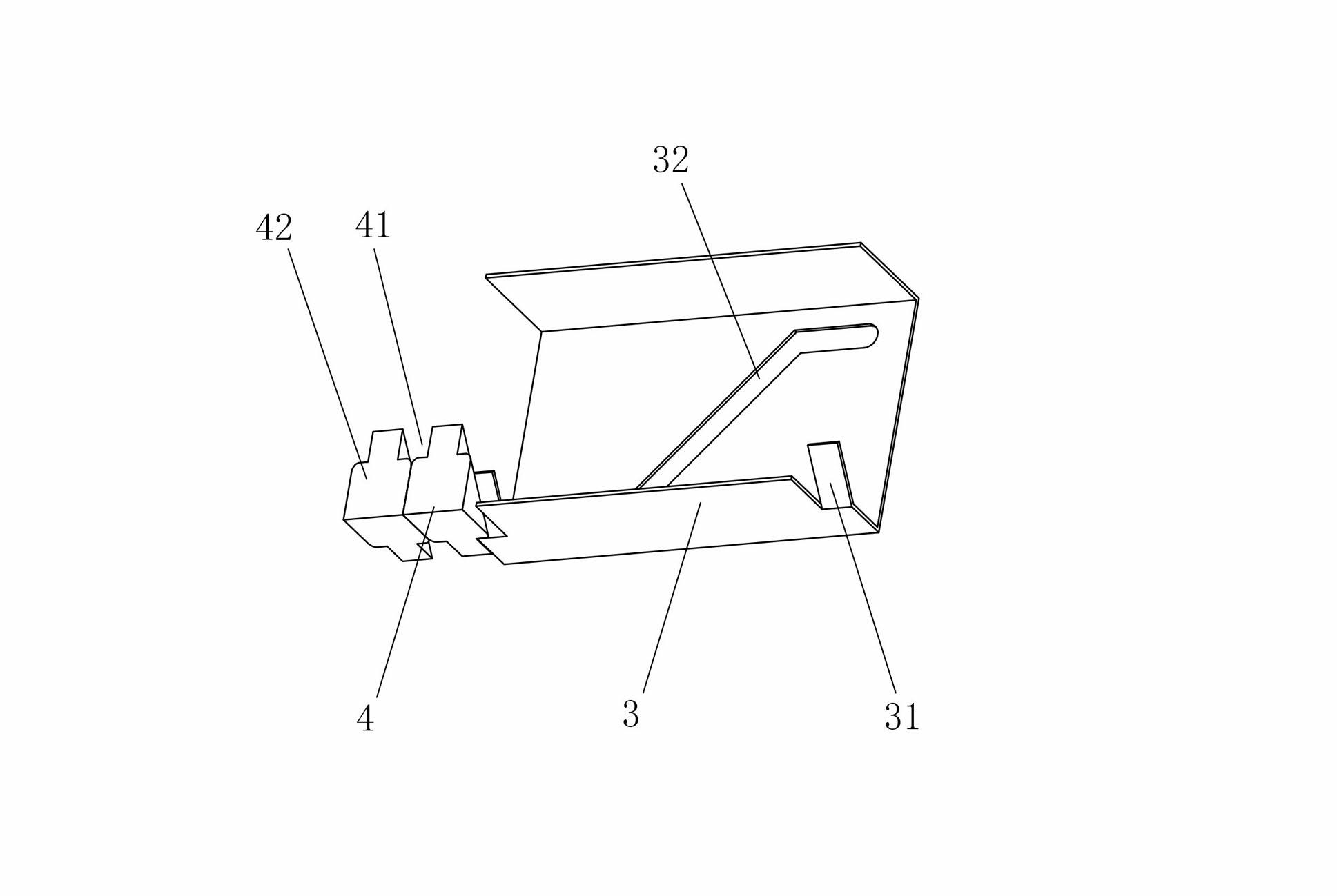
[0020] Figure 1 to Figure 3 It shows an embodiment of a louver of the present invention, the louver includes a plurality of blades 2, and a frame 1 formed by connecting a top beam 11, a bottom beam 12 and two side beams 13, and the two side beams 13 They are all channel-shaped beams, and the notch is set toward the inner side of the frame body 1. A sliding connector 3 is sleeved on both ends of each blade 2, and the blade 2 is installed between two side beams 13 through the sliding connector 3. , the sliding connecting piece 3 is slidably arranged in the notch of the side beam 13, and a clip bar 4 for adjusting the distance is clamped between two adjacent sliding connecting pieces 3. The louver of the present invention installs the blade 2 between the two side beams 13 through the sliding connector 3, and adjusts the distance between the blades 2 by clamping the clip 4 between the two adjacent sliding connectors 3, Its overall structure is simple and reliable, and the instal...


PUM


Abstract

The invention discloses a shutter. The shutter comprises a plurality of blades, and a frame body which is formed by connecting a top beam, a bottom beam and two side beams; the two side beams are both trough beams, and notches face the inner side of the frame body; a sliding connection piece is sleeved at two ends of each blade respectively, the blade is arranged between the two side beams through the sliding connection piece; each sliding connection piece is arranged in the notches of the side beams in a sliding way; and a clamp strip for adjusting a space is arranged between two adjacent sliding connection pieces. The shutter has the advantages of simple structure, and low cost, and is convenient to install; and the space between the blades can be adjusted conveniently.

Description

technical field [0001] The invention relates to shutter doors and windows made of metal, in particular to a shutter. Background technique [0002] The shutters made of metal have high strength and good protection, especially the shutters made of zinc-coated steel plates on the surface have strong anti-rust and anti-corrosion capabilities, and the material cost is low and cheap. At present, they are gradually replacing aluminum alloy shutters on the market. However, the blades of the galvanized steel louvers with surface spraying are all stamped and bent, and it is inconvenient to set screw holes at both ends of the blades. Put the blade fixing pads in the fixing holes, and use the blade fixing pads to position the blades. When installing, insert one end of all the blades into the blade fixing pads of one frame one by one, and then connect each blade fixing pad of the other frame with the corresponding The other ends of the blades are aligned one by one. If there is a misali...

Claims


Application Information

Patent Timeline
Patent Type & Authority Applications(China)
IPC IPC(8): E06B9/02E06B9/28E06B9/384
Inventor 谢斌泉
Owner HUNAN GOLDWELL NEW MATERIALS TECH CO LTD
Why Eureka
Try Eureka