Rolling friction-wear testing machine capable of controlling friction coefficient and slip frequency on line

A rolling friction and wear test technology, applied in the direction of testing wear resistance, etc., can solve the problems of inability to realize friction and wear experiments with constant friction coefficient, inability to measure and compensate for errors in actual slip and friction, and avoid braking resistance. overheating effect

Inactive Publication Date: 2013-06-12
INST OF MECHANICS - CHINESE ACAD OF SCI
View PDF4 Cites 2 Cited by
  • Summary
  • Abstract
  • Description
  • Claims
  • Application Information

AI Technical Summary

Problems solved by technology

[0004] 1. It is impossible to measure and compensate the actual slip and friction error caused by the diameter change of the sample after wear during the experiment
[0005] 2. Friction and wear experiments with constant friction coefficient cannot be realized

Method used


Image

  • Rolling friction-wear testing machine capable of controlling friction coefficient and slip frequency on line
  • Rolling friction-wear testing machine capable of controlling friction coefficient and slip frequency on line

Examples


Embodiment Construction

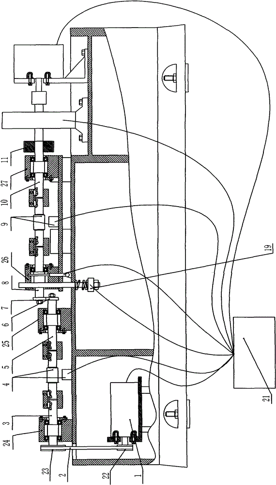
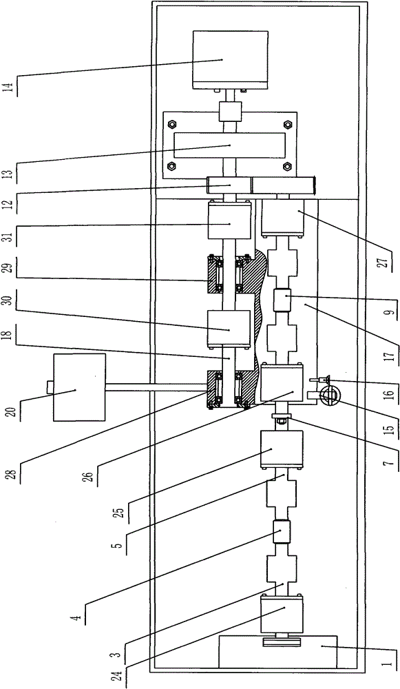
[0036] Such as figure 1 , 2 As shown, the present invention specifically includes: a lower sample shaft platform 32, an upper sample shaft platform 17 and a pressure balance loading device, and a first transmission shaft is rotatably provided on the lower sample shaft platform 32 through the first bearing seats 24, 25 3, 5, the power input end of the first transmission shaft 3, 5 is connected with the power output end of the first motor 1, and the lower sample 6 is installed on the power output end of the first transmission shaft 3, 5. On the lower sample shaft platform 32, the second transmission shaft 18 is also installed through the second bearing blocks 30, 31, and the power input end of the second transmission shaft 18 is connected with the power output end of the second motor 14. On the second transmission shaft 14 Drive gear 12 is also installed on it.

[0037] The upper sample shaft platform 17 is rotatably mounted on the second transmission shaft 18 through the four...


PUM


Abstract

The invention discloses a rolling friction-wear testing machine capable of controlling friction coefficient and slip frequency on line. The rolling friction-wear testing machine comprises a lower sample shaft platform and an upper sample shaft platform, wherein the lower sample shaft platform is provided with a first transmission shaft by a first bearing pedestal, the power input end of the firsttransmission shaft is connected with the power output end of a first motor, and a lower sample is arranged at the power output end of the first transmission shaft; a second transmission shaft is arranged on the lower sample shaft platform, the power input end of the second transmission shaft is connected with the power output end of a second motor, and the second transmission shaft is also provided with a driving transmission gear; the upper sample shaft platform is rotatablely arranged on the second transmission shaft by a fourth bearing pedestal, a third transmission shaft is arranged on the upper sample shaft platform, the power input end of the third transmission shaft is provided with a driven transmission gear meshed with the driving transmission gear, and an upper sample is arranged at the power output end of the third transmission shaft. By using the testing machine disclosed by the invention, rolling friction-wear tests under different slip frequency can be easily realized.

Description

technical field [0001] The invention relates to a rolling friction and wear test device, in particular, it can control the friction coefficient and slip difference on-line, measure the change of sample diameter in real time and compensate the measurement error of the friction coefficient and slip difference caused by the diameter change. Background technique [0002] At present, the known rolling friction and wear testing machine is powered by a motor, and the gears distribute the power to the two shafts of the upper and lower samples, and the two shafts drive the upper and lower samples to roll against each other to realize the rolling friction test. For example, the prior art CN201060144Y discloses a rolling friction and wear testing machine, which includes three driving stepper motors in different orientations, a torque sensor, a two-dimensional mobile platform, a force sensor, a rolling load module and a computer program control module. , the stepping motor drives the mo...

Claims


Application Information

Patent Timeline
Patent Type & Authority Patents(China)
IPC IPC(8): G01N3/56
Inventor 邢旭辉杨明江李正阳王红才
Owner INST OF MECHANICS - CHINESE ACAD OF SCI
Why Eureka
Try Eureka