Two-stage beam shrinkage system based on photonic crystal resonant cavity and manufacturing method for two-stage beam shrinkage system

A photonic crystal and beam-shrinking system technology, applied in the optical field, can solve the problems of reducing device integration, restricting applications, complicating the structure of graded waveguides, etc., and achieving the effects of improving integration, small output spot, and low loss

Inactive Publication Date: 2013-01-23
CHANGCHUN INST OF OPTICS FINE MECHANICS & PHYSICS CHINESE ACAD OF SCI
View PDF2 Cites 0 Cited by
  • Summary
  • Abstract
  • Description
  • Claims
  • Application Information

AI Technical Summary

Problems solved by technology

But at the same time, the introduction of optical devices will complicate the structure of the graded waveguide and reduce the integration of the device
In addition, at the sub-micron scale of photonic crystal devices in the optical communication band, the diffraction effect of geometric optical devices is very obvious, which limits the application of the above two methods

Method used


Image

  • Two-stage beam shrinkage system based on photonic crystal resonant cavity and manufacturing method for two-stage beam shrinkage system
  • Two-stage beam shrinkage system based on photonic crystal resonant cavity and manufacturing method for two-stage beam shrinkage system
  • Two-stage beam shrinkage system based on photonic crystal resonant cavity and manufacturing method for two-stage beam shrinkage system

Examples


Embodiment Construction

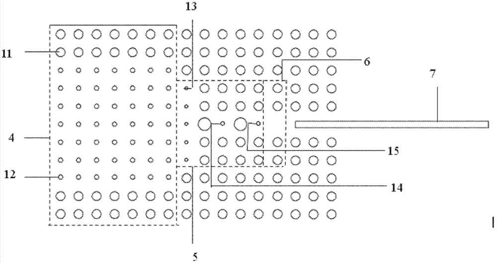
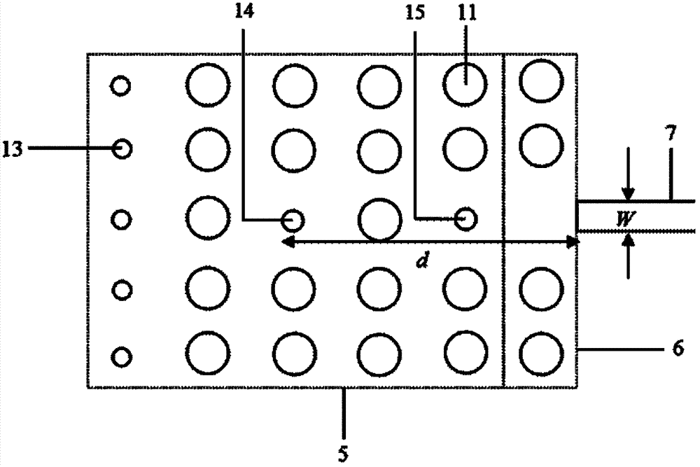
[0057] Such as figure 1 , 2 As shown, the two-stage beam shrinkage system based on the photonic crystal resonator of the present invention is composed of W7 type photonic crystal waveguide 4, photonic crystal resonator 5, W1 type photonic crystal waveguide 6 and nanowire waveguide 7, which are arranged in close order; the photonic crystal resonator The cavity 5 is formed by adding point defects 14 into the photonic crystal, and a row of dielectric pillars 13 is distributed at the connection between the photonic crystal resonator 5 and the W7-type photonic crystal waveguide 4, and the row of dielectric pillars constitutes a coupling area; the photonic crystal resonator 5 and the W1-type One or more coupling medium pillars 15 are distributed at the junction of the photonic crystal waveguide and corresponding to the point defect 14; the whole system is integrated on one substrate.

[0058] The electromagnetic wave (1550nm) of the characteristic frequency is incident from the W7 ...


PUM


Abstract

The invention relates to a two-stage beam shrinkage system based on a photonic crystal resonant cavity and a manufacturing method for the two-stage beam shrinkage system. The system consists of a W7-type photonic crystal waveguide, a photonic crystal resonant cavity, a W1-type photonic crystal waveguide and a nanowire waveguide which are closely connected and arranged in turn, wherein the photonic crystal resonant cavity is formed by adding point defects into a photonic crystal, a row of medium columns are distributed at the joint between the photonic crystal resonant cavity and the W7-type photonic crystal waveguide, and a coupling area is formed by the row of medium columns; one or more coupling medium columns are distributed at the joint between the photonic crystal resonant cavity andthe W1-type photonic crystal waveguide and at a position corresponding to the point defects; and the whole system is integrated on a substrate. Due to the adoption of a two-stage compression structure, a light beam is compressed by first-stage compression and second-stage compression, so that the effects of a higher compression ratio and a smaller emitting light spot are achieved, and the system has high coupling efficiency and low consumption of light information transmitted among devices; in addition, compared with a system with gradient waveguides, the system has the advantages that: the volume of a device is greatly reduced, and the integration level of the device is improved.

Description

Technical field: [0001] The invention belongs to the field of optical technology, and relates to a microstructure photonic crystal element, in particular to a two-stage beam shrinkage system based on a photonic crystal resonant cavity and a manufacturing method thereof. Background technique: [0002] Photonic crystals are artificial microstructures formed by substances with different dielectric constants arranged periodically in space. In recent years, optoelectronic functional devices based on photonic crystal materials have received extensive attention. Photonic crystal optoelectronic devices such as photonic crystal waveguides, filters, optical switches, and couplers have been used The report has laid a good foundation for the realization of large-scale optoelectronic integration and all-optical networks in the future. [0003] Photonic crystals are artificial microstructures formed by periodic arrangements of media with different refractive indices. When electromagnetic...

Claims


Application Information

Patent Timeline
Patent Type & Authority Patents(China)
IPC IPC(8): G02B27/09G02B6/122G02B6/24G02B6/13
Inventor 王维彪梁静秋梁中翥周建伟
Owner CHANGCHUN INST OF OPTICS FINE MECHANICS & PHYSICS CHINESE ACAD OF SCI
Why Eureka
Try Eureka