
A valve-type microfluidic two-component electrospinning nozzle

An electrospinning, two-component technology, used in textiles and papermaking, filament/thread forming, fiber processing, etc., can solve the problems of capillary blockage, difficult to clean, complex structure, etc. simple structure

Active Publication Date: 2016-09-21
BEIJING UNIV OF CHEM TECH
View PDF6 Cites 0 Cited by
  • Summary
  • Abstract
  • Description
  • Claims
  • Application Information

AI Technical Summary

Problems solved by technology

[0003] The capillary was once one of the most critical components of electrospinning. The diameter of the capillary determines the diameter of the fiber to a large extent, but the diameter of the capillary cannot obtain fibers of other diameters, and the capillary is prone to clogging during the spinning process. Seriously affect the continuous spinning, and it is difficult to clean, and the output is also low
However, the output of the needle-free nozzle invented in recent years has been greatly improved, but the structure is relatively complicated, and it is still prone to clogging, and the spinning material is single, which cannot meet the demand for multi-component fiber materials, and the flow rate cannot be controlled in real time.
The existing invention patent "a microfluidic electrospinning device" (CN203754860 U), this patent is to realize the control of micro flow through two syringes and the control valve between the syringe and the barrel, the barrel and the outlet, which can Control the amount of entry, but the flow at the nozzle is uncontrollable, and the device is placed horizontally, it is impossible to determine whether the barrel is full, and the flow control at the nozzle is even more difficult to achieve

Method used


Image

  • A valve-type microfluidic two-component electrospinning nozzle
  • A valve-type microfluidic two-component electrospinning nozzle
  • A valve-type microfluidic two-component electrospinning nozzle

Examples


Embodiment Construction

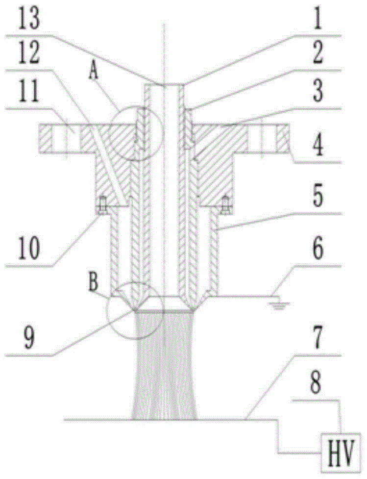
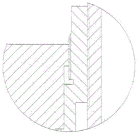
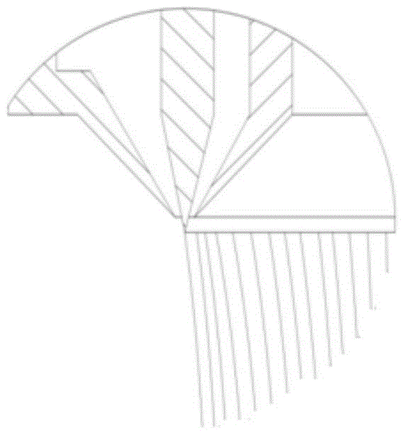
[0015] A valve-type microfluidic two-component electrospinning nozzle of the present invention, the schematic diagram of the nozzle is as follows figure 1 As shown, it mainly includes inner material cylinder 1, split column cylinder 2, inner material cylinder inlet 3, connector 4, outer material cylinder 5, grounding 6, receiving plate 7, high-voltage electrostatic generator 8, spinning tip 9 , a fixing screw 10, a fixing screw hole 11, an outer barrel feeding port 12 and an auxiliary air inlet 13. The inner material cylinder 1, the splitter cylinder 2 and the connecting piece 4 are coaxially connected through threads from the inside to the outside. It is connected with the outer material cylinder 5 by screws 10, the outer material cylinder is located under the connector, the outer material cylinder 5 is grounded, and the receiving plate 7 is located directly under the entire nozzle and communicated with the high-voltage electrostatic generator 8.

[0016] The present inventi...


PUM


Abstract

The invention provides a valve type microfluidic bi-component electrostatic spinning nozzle which mainly comprises a connecting piece, a shunting column casing, an inner charging barrel, an outer charging barrel, a screw, a receiving plate, a high-voltage electrostatic generator and a heating system. The inner charging barrel, the shunting column casing and the connecting piece are sequentially connected by coaxial threads from inside to outside. The connecting piece is connected with the outer charging barrel through the screw and the outer charging barrel is arranged under the connecting piece. Two feeding holes are formed, the feeding holes comprise the inner feeding hole and the outer feeding hole, and the inner feeding hole and the outer feeding hole are both formed in the upper surface of the connecting piece. The receiving plate is placed under a nozzle body and is connected with the high-voltage electrostatic generator. The valve type microfluidic bi-component electrostatic spinning nozzle is simple in structure, capable of achieving the micro-control of flow and preparing composite fibers of different component proportions, and not prone to being plugged. According to the production demand, the fibers of different dimensions are prepared by adjusting seam distances and technological parameters, the application range is wide, and the yield can be improved by changing the number of nozzles or the nozzle modes.

Description

technical field [0001] The invention relates to a valve-type microfluidic two-component electrostatic spinning nozzle, which belongs to the field of electrostatic spinning. Background technique [0002] With the rapid development of science and technology, society has put forward higher requirements for nanomaterials. Electrospinning has attracted much attention because it can prepare nanoscale fibers and has become a research hotspot in recent years. The fastest and most effective method. [0003] The capillary was once one of the most critical components of electrospinning. The diameter of the capillary determines the diameter of the fiber to a large extent, but the diameter of the capillary cannot obtain fibers of other diameters, and the capillary is prone to clogging during the spinning process. It seriously affects the continuous spinning, and it is difficult to clean, and the output is also low. However, the output of the needle-free nozzle invented in recent years ...

Claims


Application Information

Patent Timeline
Patent Type & Authority Patents(China)
IPC IPC(8): D01D5/00
CPCD01D5/0069
Inventor 杨卫民张罗谭晶李好义谢鹏程焦志伟阎华丁玉梅
Owner BEIJING UNIV OF CHEM TECH
Learn More