Push switch

A switch and push operation technology, applied in the field of push switches with 2-level action, can solve the problems of poor operating tactile sensation, unstable flipping action of the second movable contact 931, loss of balance of the first movable contact 930, etc. The effect of stable action and stable operation tactile sensation

Active Publication Date: 2015-01-21
ALPS ALPINE CO LTD
View PDF4 Cites 0 Cited by
  • Summary
  • Abstract
  • Description
  • Claims
  • Application Information

AI Technical Summary

Problems solved by technology

Therefore, there is a problem that the peripheral fixed contacts 923 and 924 are arranged only at two symmetrical positions, so when the second movable contact 931 is turned over, the first movable contact 930 is pressed unevenly. In this case, the first movable contact 930 is out of balance, the flipping action of the second movable contact 931 becomes unstable, and the tactile feeling of operation becomes poor.

Method used


Image

  • Push switch
  • Push switch
  • Push switch

Examples


no. 1 Embodiment approach

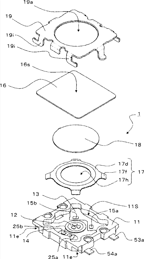
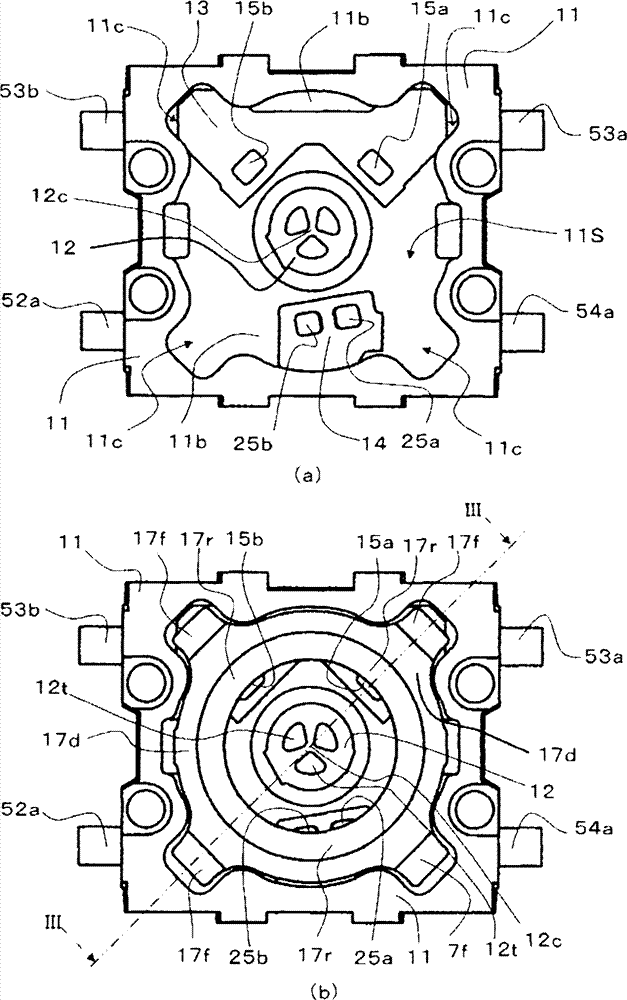
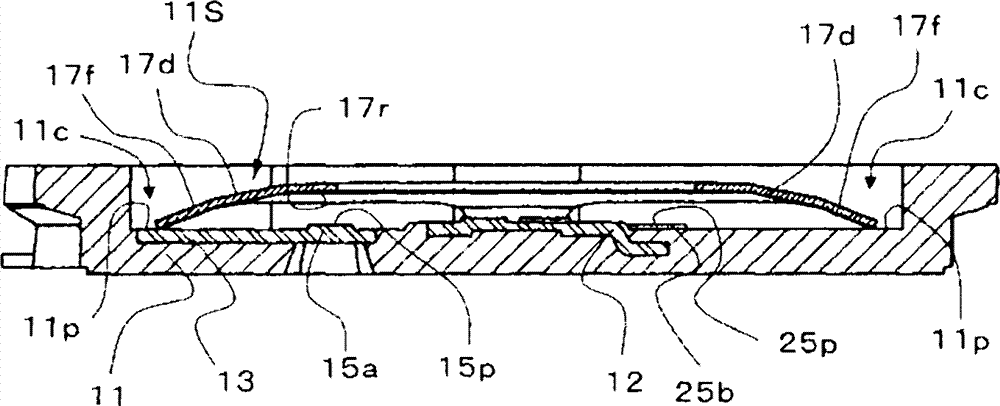
[0038] figure 1 It is an exploded perspective view illustrating the push switch 1 according to the first embodiment of the present invention. figure 2 It is a figure explaining the push switch 1 of 1st Embodiment of this invention, figure 2 (a) is a plan view of the casing 11, figure 2 (b) is a plan view in which the first movable contact 17 is attached to the casing 11 . image 3 yes figure 2 (b) A sectional view taken along line III-III.

[0039] Such as figure 1 As shown, the push switch 1 is configured to include: a casing 11 having a storage portion 11S; a central fixed contact portion 12, a first peripheral fixed contact portion 13, and a second peripheral fixed contact portion 14 arranged in the storage portion 11S; The first movable contact 17 that is in contact with the first peripheral fixed contact portion 13 and the second peripheral fixed contact portion 14 by being turned over by pressing operation; The second movable contact 18. In addition, the cov...

Deformed example 1

[0078] In the above-mentioned embodiment, the second movable contact 18 has a simple arch shape, but as Figure 9 As shown, the second movable contact 28 may be provided with a concave protrusion 28a at the top portion of the arched portion 28d. Therefore, even if the pressing position and the pressing angle are slightly deviated during the pressing operation, the entire top portion of the arched portion 28d can be pressed by the concave protrusion 28a, so that the pressing operation can be reliably performed. In addition, when a key top having a convex portion corresponding to the concave portion is used, the concave portion overlaps the convex portion, and the positional displacement does not occur, so that the pressing operation can be reliably performed.

Deformed example 2

[0080] Additionally, if Figure 10 As shown, the structure may be such that a small spacer 56 is inserted between the second movable contact 18 and the film 16 in the above-mentioned embodiment. Therefore, even if the pressing position and the pressing angle are slightly deviated during the pressing operation, the small spacer 56 presses the entire top portion of the arch portion 18d, so that the pressing operation can be reliably performed.


PUM


Abstract

PROBLEM TO BE SOLVED: To provide a push switch having a two-step operation capable of stably providing operation feeling.SOLUTION: This push switch has: a casing 11 having a housing part 11S; a center stationary contact part 12, a first peripheral contact part 13, and a second peripheral stationary contact 14 which are disposed in the housing part; a first movable contact 17 which can be inversely operated by pressing operation, has a plurality of leg parts 17f and a dome part 17d having a hole 17h in the center thereof, and is brought into contact with the first peripheral stationary contact part and the second peripheral stationary contact part; and a second movable contact 18 which can be inversely operated by pressing operation, has a dome part 18, is placed on the first movable contact so as to cover the hole part, and can be brought into contact with and separated from the center stationary contact part. The first peripheral stationary contact part has at least two or more contact parts 15, the second peripheral stationary contact part has at least one or more contact parts 25, and a plurality of contact parts 15, 25 are disposed at three locations where the first movable contact can be supported by almost three points and are disposed face to face so as to be able to come into contact with the first movable contact when the first movable contact inversely operates.

Description

technical field [0001] The present invention relates to a push switch in which a movable contact is turned over by a push operation to connect and disconnect the contact, and particularly relates to a push switch with a two-stage operation. Background technique [0002] Conventionally, the push switch used in the shutter portion of a mobile phone or a camera is desired to have a structure capable of performing a second-stage operation in addition to the first-stage operation. In order to realize this two-stage operation, a reed contact is used at two positions, or a method of overlapping two arch-shaped contacts. [0003] In Patent Document 1, such as Figure 11 As shown, a push switch in which two arcuate contacts are overlapped is proposed. figure 1 The shown push switch includes: a switch box 921, a central fixed contact 922 in the center of the recess of the switch box 921, mutually independent peripheral fixed contacts 923 arranged at two points symmetrical positions ...

Claims


Application Information

Patent Timeline
Patent Type & Authority Patents(China)
IPC IPC(8): H01H13/64H01H13/48
CPCH01H1/06H01H13/14H01H13/48H01H2221/058H01H2225/002
Inventor 加藤秀和高桥一成田泽俊彦水越寿彰天野和彦富永晴夫
Owner ALPS ALPINE CO LTD
Why Eureka
Try Eureka