
Light source stroboscopic detection system and method based on machine vision detection

A technology of machine vision detection and detection system, which is applied in the direction of machine/structural component testing, optical instrument testing, and optical performance testing. Effects of moving trajectory, improving filtering effect, and improving accuracy

Active Publication Date: 2021-03-16
成都新西旺自动化科技有限公司
View PDF7 Cites 0 Cited by
  • Summary
  • Abstract
  • Description
  • Claims
  • Application Information

AI Technical Summary

Problems solved by technology

The light source has the function of amplifying the features and defects of the image, weakening the confusion and the background, and directly affecting the quality of the input data. When selecting the light source of the detection system, a specific light source is usually selected for different application examples, so that the effect of machine vision detection The strobe of the light source is an important factor affecting the test results. If the stroboscopic unqualified light source is installed in the machine vision inspection system for inspection, it will lead to large errors in the test results, and even directly cause the test to fail.

Method used


Image

  • Light source stroboscopic detection system and method based on machine vision detection
  • Light source stroboscopic detection system and method based on machine vision detection
  • Light source stroboscopic detection system and method based on machine vision detection

Examples


specific Embodiment

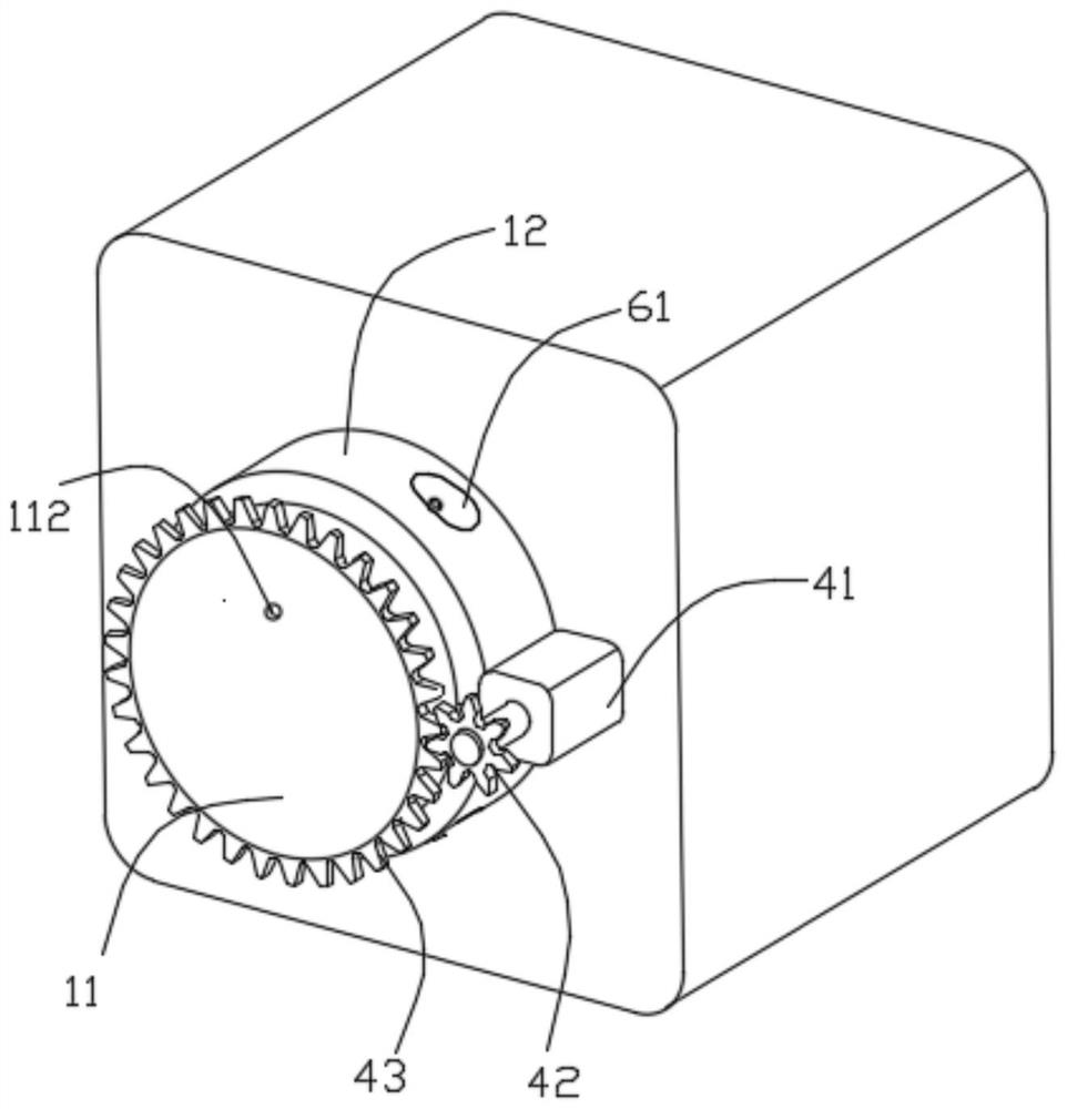
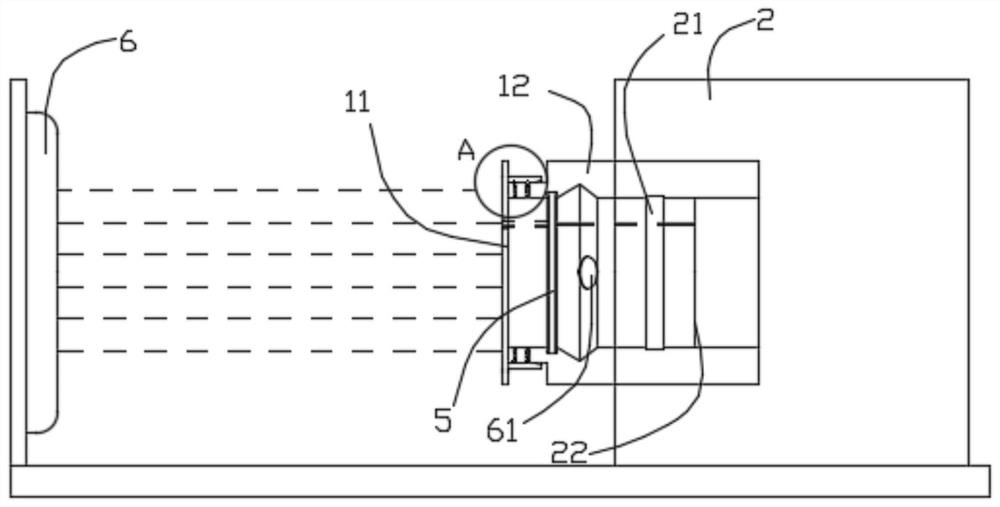
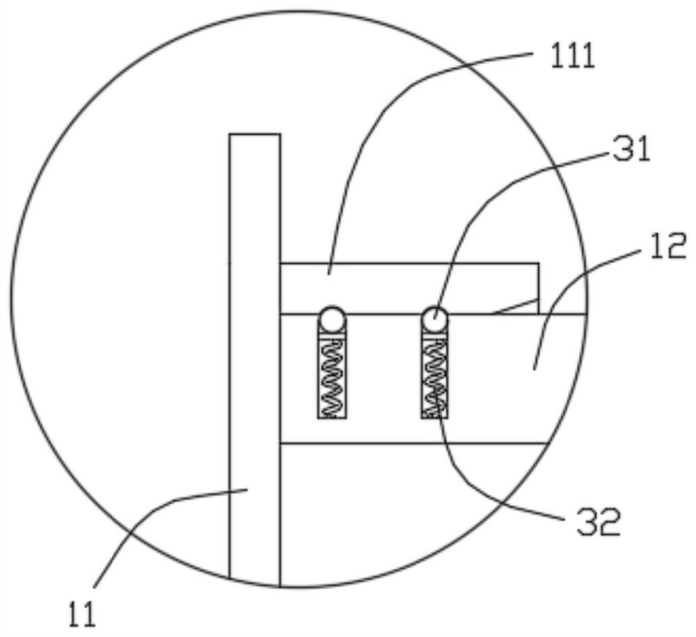
[0040] see Figure 1-11 Shown, the specific embodiment that the present invention provides is as follows:

[0041] A light source stroboscopic detection system based on machine vision detection in this embodiment includes a collection device and a control unit, the collection device is used to collect detection images of the stroboscopic light source to be detected, and the collection device includes a shading mechanism and a camera, The camera is a high-speed camera, which can capture and expose images in a very short time. The shading mechanism includes a shading cover 11 and a shading housing 12; the shading housing 12 is cylindrical along the axis of the camera lens 21. The tail end of the light-shielding housing 12 is connected to the camera body 2, and the free end opposite to the tail end is rotated and matched with the light-shielding cover by setting a rotating part, so that the light-shielding cover is relatively shielded from the central axis of the camera lens. Th...


PUM


Abstract

The invention discloses a light source stroboscopic detection system and method based on machine vision detection. The light source stroboscopic detection system based on machine vision detection comprises an acquisition device and a control unit. The acquisition device is used for acquiring a stroboscopic detection image of a light source to be detected, the acquisition device comprises a shadingmechanism and a camera, the camera is a high-speed camera, and the shading mechanism comprises a shading cover and a shading shell; the shading cover is provided with a lighting hole, and the shadingmechanism is provided with a power part, comprises a rotating motor arranged outside the shading shell and is used for driving the shading cover to rotate relative to the shading shell around the central axis of a camera lens; and the control unit is used for adjusting the rotating speed of the rotating motor to control the rotating speed of the lighting hole in the shading cover and enabling thecamera to perform exposure work for a period of time required by one-circle rotation of the lighting hole when the rotating speed of the lighting hole is constant. The system has the beneficial effects that the detection image with dark spots for calculating stroboflash of the light source to be detected can be acquired so that the stroboscopic detection process of the light source to be detectedis simplified, and meanwhile, stroboscopic calculation complexity is reduced.

Description

technical field [0001] The invention belongs to light source flicker detection technology related to machine vision detection, and in particular relates to a light source flicker detection system and method based on machine vision detection. Background technique [0002] Machine vision detection refers to converting the ingested target into an image signal through machine vision products, and sending it to a dedicated image processing system, and converting it into a digital signal according to pixel distribution, brightness, color and other information; the image system performs various calculations on these signals To extract the characteristics of the target, use the machine instead of the human eye to make measurement and judgment, and then control the on-site equipment action according to the judgment result. Among them, the machine vision inspection system is mainly composed of camera, lens and light source, which is the basis of vision inspection. The light source ha...

Claims


Application Information

Patent Timeline
IPC IPC(8): G01M11/02
CPCG01M11/02G01M11/0207
Inventor 王盼杨玉梅张勇刘中
Owner 成都新西旺自动化科技有限公司
Learn More