Pedal mounting bracket and automatic welding machine for welding pedal mounting bracket
An automatic welding machine and mounting bracket technology, which is applied in the layout of pedals or ladders, welding equipment, welding equipment, etc., can solve the problems of low production efficiency, hidden dangers, inaccurate positioning of welcome pedal brackets, etc., and achieve space utilization. High, secure and reliable connection effect
- Summary
- Abstract
- Description
- Claims
- Application Information
AI Technical Summary
Problems solved by technology
Method used
Image
Examples
Embodiment 1
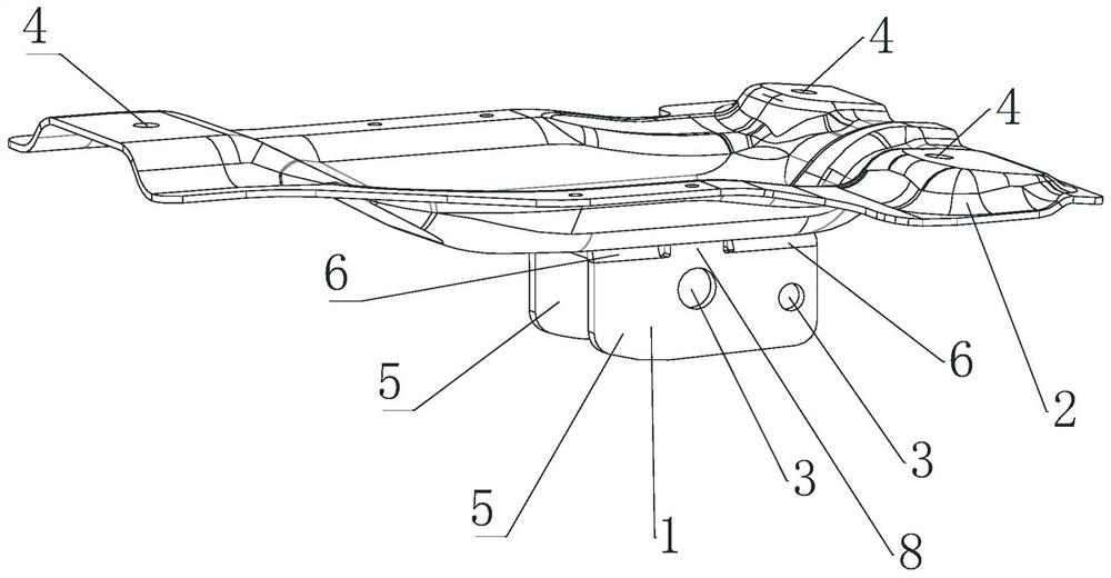
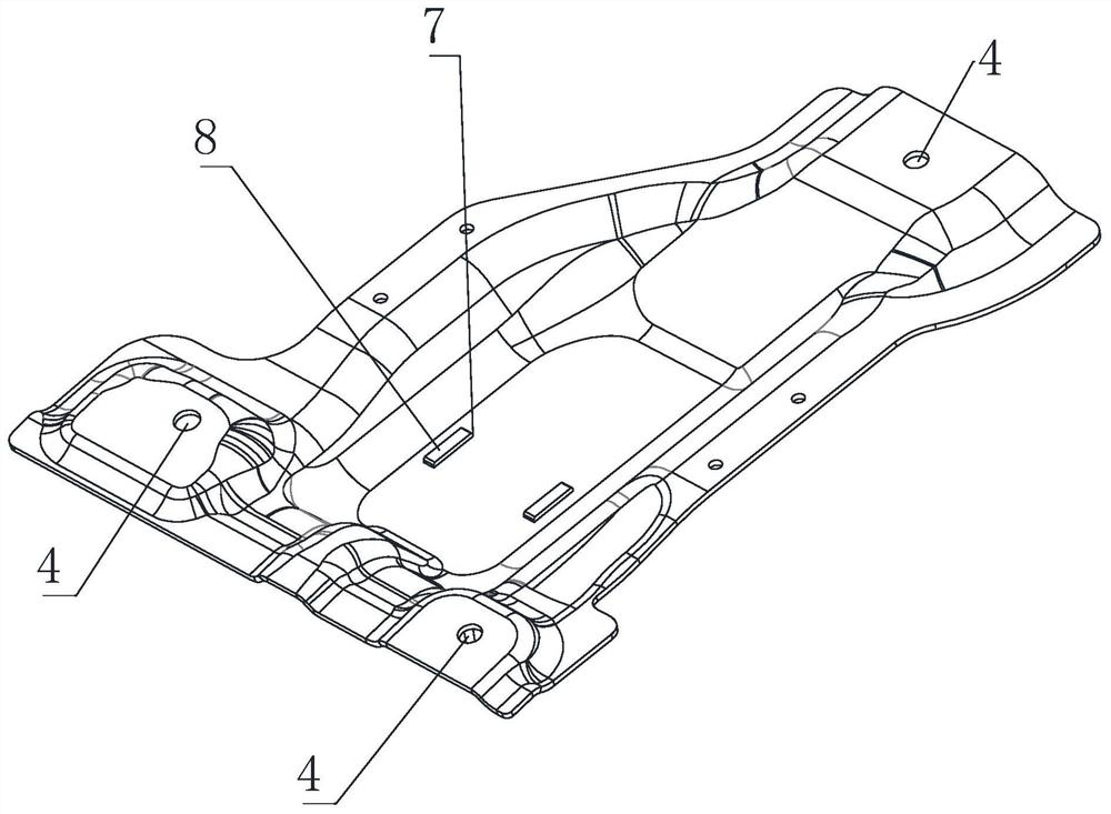
[0030] Such as Figure 1 to Figure 2As shown, a pedal mounting bracket includes a base plate 2 for fixing to the vehicle body and a U-shaped ear seat 1 for fixing to the pedal body. The U-shaped ear seat 1 surrounds a U-shaped assembly groove, and the U-shaped ear seat 1 A first installation hole 3 for connecting with the pedal is opened on the top, the bottom plate 2 and the U-shaped ear seat 1 are fixed by welding, and a second installation hole 4 is opened on the bottom plate 2 . The U-shaped ear seat 1 includes two mounting ears 5 and a welding plate 6 connected to the mounting ears 5. The welding plate 6 is welded and fixed to the bottom plate 2. A slot 7 is opened on the bottom plate 2. The U-shaped ear seat 1 is arranged at one end close to the bottom plate 2. There is a socket 8 plugged into the slot 7 . The number of the first mounting holes 3 is two, corresponding to the installation of the inner transmission arm and the outer transmission arm respectively. Three s...
Embodiment 2
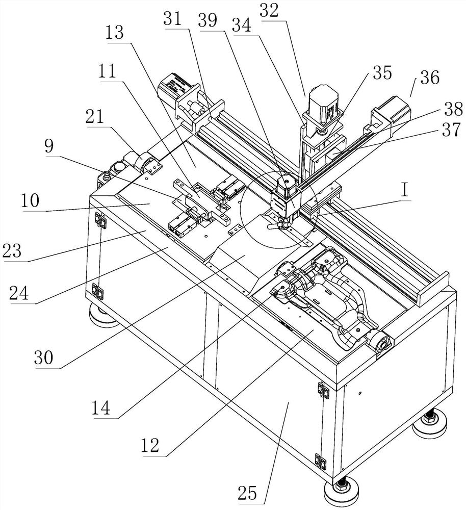
[0033] Such as Figure 1 to Figure 4 As shown, the present embodiment provides an automatic welding machine for welding the welding pedal installation bracket of Embodiment 1, including a support stand 23, and the support stand 23 includes a welding operation table 24, and the welding operation table 24 is equipped with a The support plate 9 of the support, welding mechanism is also installed on the welding operation platform 24, and welding mechanism comprises the first screw mandrel assembly 31 that is fixed on the welding operation platform 24 and the welding frame 32 that is installed on the first screw mandrel assembly 31, the second The threaded screw assembly 31 drives the welding frame 32 to move left or right. The welding frame 32 includes a first mounting base installed on the first screw assembly 31 and a vertical vertical mounting frame mounted on the first mounting base 34. The second screw rod assembly 35 in the vertical direction is installed on the vertical mou...
Embodiment 3
[0043] The difference between this embodiment and Embodiment 2 is that when the upper end surface 12 of the first support plate 9 is welded, the support plate 9 is turned over, and the welding mechanism moves to another support plate 9, and the other The U-shaped base and the bottom plate on the support plate 9 are welded. When the welding is completed, the support plate 9 is turned over, and the welding mechanism moves the first support plate 9 to weld the other side of the support plate 9.
PUM
 Abstract
Description
Claims
Application Information
 - R&D
- Intellectual Property
- Life Sciences
- Materials
- Tech Scout
- Unparalleled Data Quality
- Higher Quality Content
- 60% Fewer Hallucinations
Browse by: Latest US Patents, China's latest patents, Technical Efficacy Thesaurus, Application Domain, Technology Topic, Popular Technical Reports.
© 2025 PatSnap. All rights reserved.Legal|Privacy policy|Modern Slavery Act Transparency Statement|Sitemap|About US| Contact US: help@patsnap.com


