Flywheel battery

A flywheel battery and flywheel technology, applied in electrical components, electromechanical devices, electric components, etc., can solve the problems of inability to achieve long-term effective storage of kinetic energy, infeasible mechanical bearings, slow charging and discharging speed, etc., to facilitate mass production and maintenance. The effect of maintenance, extended service life, and increased charging speed

Inactive Publication Date: 2012-04-18
杭州英若飞科技有限公司
View PDF3 Cites 41 Cited by
  • Summary
  • Abstract
  • Description
  • Claims
  • Application Information

AI Technical Summary

Problems solved by technology

However, in the air environment, the high-speed rotating flywheel will cause extremely high wind resistance loss, which greatly consumes the energy generated when the flywheel rotates, and the energy storage capacity of the battery is small, and the charging and discharging speed is slow.
[0005] 2) It is not feasible to use mechanical bearings in flywheel batteri

Method used


Image

  • Flywheel battery
  • Flywheel battery
  • Flywheel battery

Examples


Embodiment 1

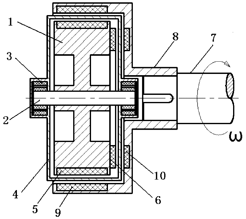
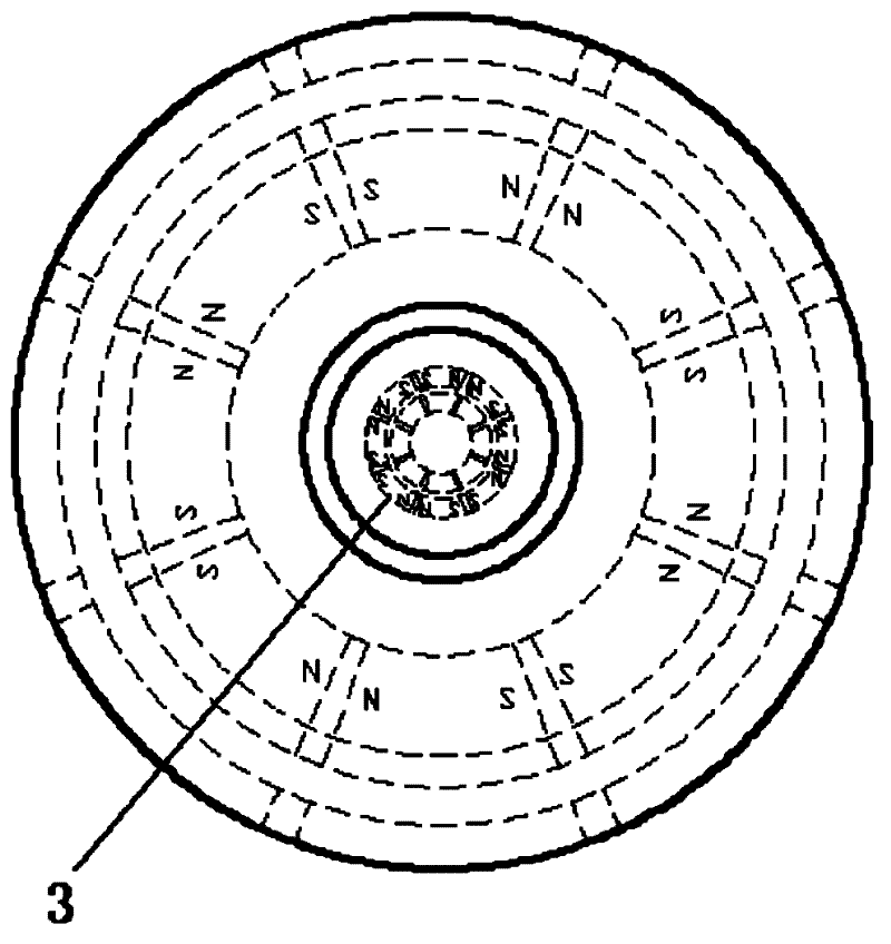
[0028] A kind of flywheel battery, such as figure 1 As shown, it includes a flywheel device and a drive device for driving the flywheel to rotate. The flywheel device includes a flywheel 1, a flywheel shaft 2, a flywheel shaft 2 with a magnetic suspension bearing 3 for supporting the flywheel shaft 2. The magnetic poles are NNSS arranged in pairs. Such as figure 2 As shown, the flywheel device further includes a vacuum enclosure 4 provided on the periphery, and the vacuum enclosure 4 is a closed thin-walled cavity made of non-magnetic material with an annular cross section. The vacuum sealing cover 4 is in interference fit with the magnetic suspension bearing 3, and the flywheel 1 is made of magnetic material or an inner magnet is fixed on the outer side of the circumferential surface of the flywheel 1. Since the flywheel 1 is directly made of magnetic material, the cost is relatively high. Therefore, in this embodiment, an axial inner magnet 5 and a radial inner magnet 6 are ...

Embodiment 2

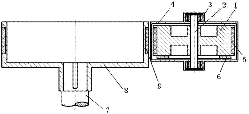
[0034] The structure of the driving device and the flywheel device in the second embodiment is similar to that in the first embodiment. The difference is that the installation positions of the driving device and the flywheel device are different, such as image 3 As shown, the flywheel device is arranged outside the circular sleeve of the rotor 8, the axis of the flywheel shaft 2 is parallel to the axis of the rotor 8, and the gap between the vacuum enclosure 4 of the flywheel device and the rotor 8 is 5 mm. The fixed structure in which the driving device and the flywheel device are arranged in parallel is an existing conventional fixing method, which is not covered by the protection scope of the present invention, so it will not be repeated.

[0035] At the same time, since the driving device and the flywheel device are arranged side by side, only the axial outer magnets 9 of the rotor 8 are parallel to the axial inner magnets of the flywheel 1, so in this embodiment, there is no...


PUM


Abstract

The invention relates to a flywheel energy storage device, in particular to a flywheel battery with a rapid charging and discharging function. The flywheel battery comprises a flywheel device and a driving device which drives the flywheel to rotate. The flywheel device comprises a flywheel, a flywheel rotating shaft and magnetic suspension bearings at the two ends of the flywheel rotating shaft. The periphery of the flywheel device is provided with a vacuum enclosed hood which is in interference fit with the magnetic suspension bearings. The flywheel is made from a magnetic material or internal magnets are fixedly arranged on the flywheel. The driving device comprises a transmission shaft and a rotor. One end of the transmission shaft is fixedly connected with the rotor, and the other end of the transmission shaft is connected with a motor or an engine. The rotor is made from the magnetic material or external magnets are arranged on the rotor. A gap is reserved between the rotor of the driving device and the flywheel device. The axis of the rotor is parallel to or overlapped with that of the flywheel rotating shaft. The flywheel and the rotor drive each other through a magnetic force. By the flywheel battery, energy storage capacity can be improved and service life can be prolonged; and the flywheel battery is convenient to produce in batches, maintain and service.

Description

Technical field [0001] The invention relates to a flywheel energy storage device, in particular to a flywheel battery capable of rapid charging and discharging. Background technique [0002] At present, the more commonly used batteries in people's production and life are mostly chemical batteries, which convert electrical energy into chemical energy for storage, and then reduce chemical energy to electrical energy for output during use. Although the current chemical battery energy storage technology has been developed very mature, chemical battery energy storage technology has disadvantages such as low energy storage density, limited charge and discharge times, which leads to a short service life, serious environmental pollution, and high requirements for working temperature. . Flywheel energy storage, which uses physical methods to achieve energy storage, has received extensive attention from various countries in recent years as an emerging electrical energy storage method. [0...

Claims


Application Information

Patent Timeline
IPC IPC(8): H02K7/02
CPCY02E60/16
Inventor 高建华
Owner 杭州英若飞科技有限公司
Why Eureka
Try Eureka