
Solar energy storage system with coupled photo(electro)chemical cell and fuel cell

A fuel cell and photochemical cell technology, applied in the field of solar energy storage system and green energy storage, to achieve the effect of increasing energy storage capacity, expanding area and supporting long-term operation

Inactive Publication Date: 2012-03-14
DALIAN INST OF CHEM PHYSICS CHINESE ACAD OF SCI
View PDF6 Cites 9 Cited by
  • Summary
  • Abstract
  • Description
  • Claims
  • Application Information

AI Technical Summary

Problems solved by technology

This new concept solar energy storage and recycling system and method, which uses water as the medium and sunlight as the input energy, is coupled with the hydrogen production technology of the photo(electro)chemical cell and the hydrogen-oxygen fuel cell technology, and has not yet been reported.

Method used


Image

  • Solar energy storage system with coupled photo(electro)chemical cell and fuel cell
  • Solar energy storage system with coupled photo(electro)chemical cell and fuel cell
  • Solar energy storage system with coupled photo(electro)chemical cell and fuel cell

Examples


Embodiment 1

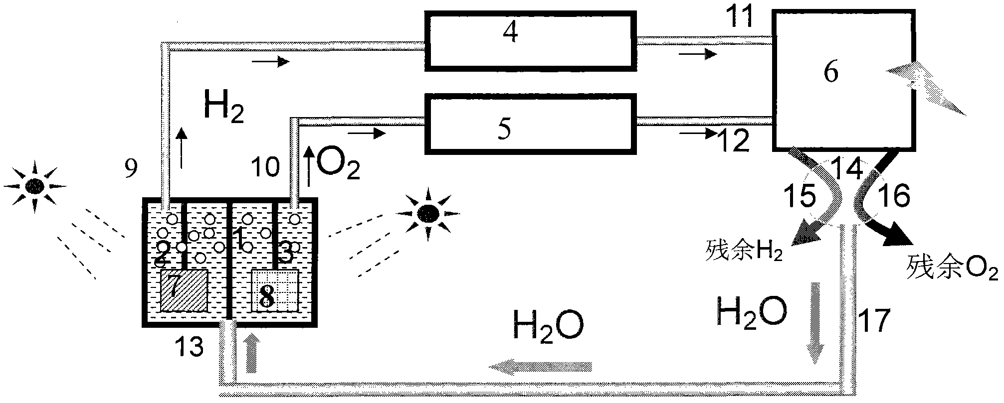
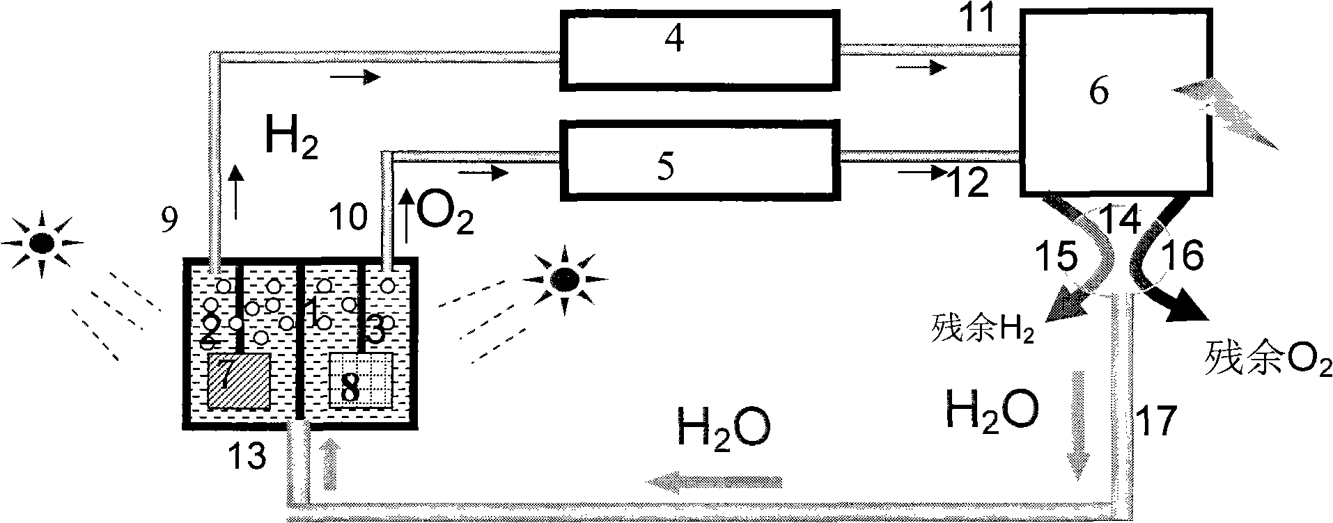
[0027] Coupled with a single photoelectrochemical unit cell and a watt-scale fuel cell, see figure 1 . The unit cell includes an electrode chamber diaphragm 1 , electrolyte solutions 2 and 3 , a counter electrode 7 (either a cathode or a photocathode) and a photoanode 8 . Photoanode material using BiVO 4 Porous film, the cathode material can be Pt, carbon and other conductive materials with low hydrogen evolution overpotential, the photocathode material can be p-type GaN film, the film thickness is controlled to be 1-10 μm, and the illumination area is 0.01m 2, the anode and the cathode or photocathode are connected with wires, and the two electrodes are separated by Nafion film. The three form a battery assembly. The battery assembly and the electrolyte are packaged in an insulating cell with an incident light receiving window to form a battery. Photoelectrochemical cell (reserve hydrogen outlet 9, oxygen outlet 10 and water inlet 13), connect the hydrogen outlet and oxygen...

Embodiment 2

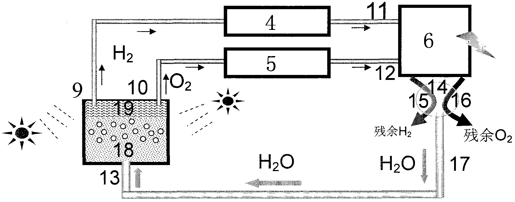
[0030] Coupled with a single photochemical unit cell and a watt-scale fuel cell, see figure 2 . The unit cell includes a photocatalyst such as a mixture 18 of GaZnON and water, a composite separation membrane 19 of hydrogen and oxygen, and a light-receiving area of ​​0.01m 2 . The hydrogen outlet 9 and the oxygen outlet 10 of the photochemical cell are connected with the hydrogen storage system 4 and the oxygen storage system 5 respectively, and the outlets of the hydrogen storage and oxygen storage systems are respectively connected with the negative electrode chamber and the positive electrode chamber of the hydrogen-oxygen fuel cell 6, and then The residual hydrogen and residual oxygen of the hydrogen-oxygen fuel cell are cooled by the gas-liquid separator 14 and then emptied through the outlet 15 and the outlet 16 respectively. Chemical battery, which constitutes a new concept solar energy storage system coupled with photochemical cells and fuel cells.

[0031] After t...


PUM

PropertyMeasurementUnit
energy conversion efficiencyaaaaaaaaaa

Abstract

The invention discloses a solar energy storage system with coupled photo(electro)chemical cell and fuel cell. The invention provides a novel-concept solar energy storage system with coupled photo(electro)chemical cell and fuel cell. The solar energy storage system comprises a photoelectrochemical cell or a photochemical cell, a hydrogen storage system, an oxygen storage system, and a hydrogen-oxygen fuel cell which are connected by using pipelines. A hydrogen inlet of the hydrogen storage system is connected to a hydrogen outlet of the photoelectrochemical cell or the photochemical cell through a pipeline. An oxygen inlet of the oxygen storage system is connected to an oxygen outlet of the photoelectrochemical cell or the photochemical cell through a pipeline. Gas outlets of the hydrogen storage system and the oxygen storage system are respectively connected to a hydrogen inlet and an oxygen inlet of the hydrogen-oxygen fuel cell through pipelines. A hydrogen outlet and an oxygen outlet of the hydrogen-oxygen fuel cell are respectively connected to a gas-liquid separator. Water vapor are cooled and connected by the gas-liquid separator, and the hydrogen outlet and the oxygen outlet of the hydrogen-oxygen fuel cell are emptied. A water outlet of the gas-liquid separator is connected to a water inlet of the photoelectrochemical cell or the photochemical cell through a pipeline.

Description

technical field [0001] The invention belongs to the technical field of renewable energy storage, and in particular relates to a solar energy storage system coupled with a photo (electro)chemical pool and a fuel cell and a green energy storage method for storing and utilizing solar energy with high efficiency and low cost. Background technique [0002] Solar energy is a clean and renewable energy source. Among all renewable energy sources, solar energy has the widest distribution, the largest energy, and the easiest access. However, solar energy is affected by regular changes in geography, day and night, and seasons, as well as random factors such as cloudy, cloudy, and rainy. The energy flow density is low, usually less than one kilowatt per square meter. In addition, energy varies with time and weather. stability and discontinuity. In order to ensure the stable operation of solar energy utilization, it is necessary to store solar energy and release it when solar energy is ...

Claims


Application Information

Patent Timeline
Patent Type & Authority Applications(China)
IPC IPC(8): H01M16/00
CPCY02B90/10Y02E60/50
Inventor 李灿施晶莹朱剑
Owner DALIAN INST OF CHEM PHYSICS CHINESE ACAD OF SCI
Learn More