Combustor

A burner, diffusion combustion technology, applied in burners, combustion chambers, combustion methods, etc., can solve the problems of increased NOx production, complicated rotating parts, increased weight and cost, etc., to suppress stripping, realize NOx, shaft Toward the effect of compact length

Active Publication Date: 2012-04-18
MITSUBISHI POWER LTD
View PDF7 Cites 12 Cited by
  • Summary
  • Abstract
  • Description
  • Claims
  • Application Information

AI Technical Summary

Problems solved by technology

[0005] However, such a conventional structure leads to an increase in weight and cost due to an increase in the length of the combustor, and also complicates the turning part, so it is ineffective for downsizing the combustor.
On the other hand, when the distance from the turning part to the fuel mixing part is shortened, there is a problem of an increase in the amount of NOx produced along with the deterioration of the bias of the air distribution as an incompatibility.

Method used


Image

  • Combustor
  • Combustor
  • Combustor

Examples


no. 1 approach 〕

[0044] Next, embodiments of the present invention will be described with reference to the drawings.

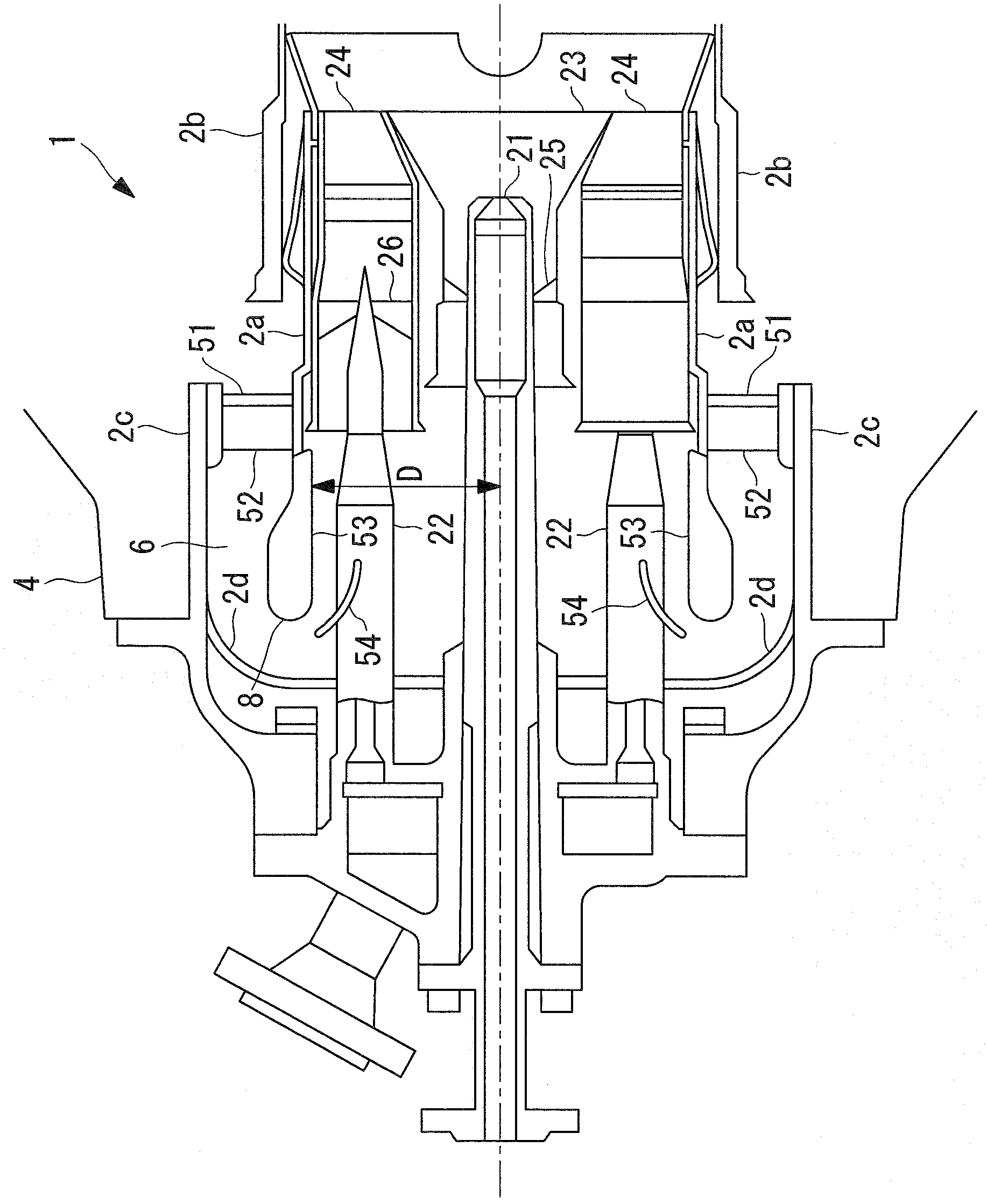
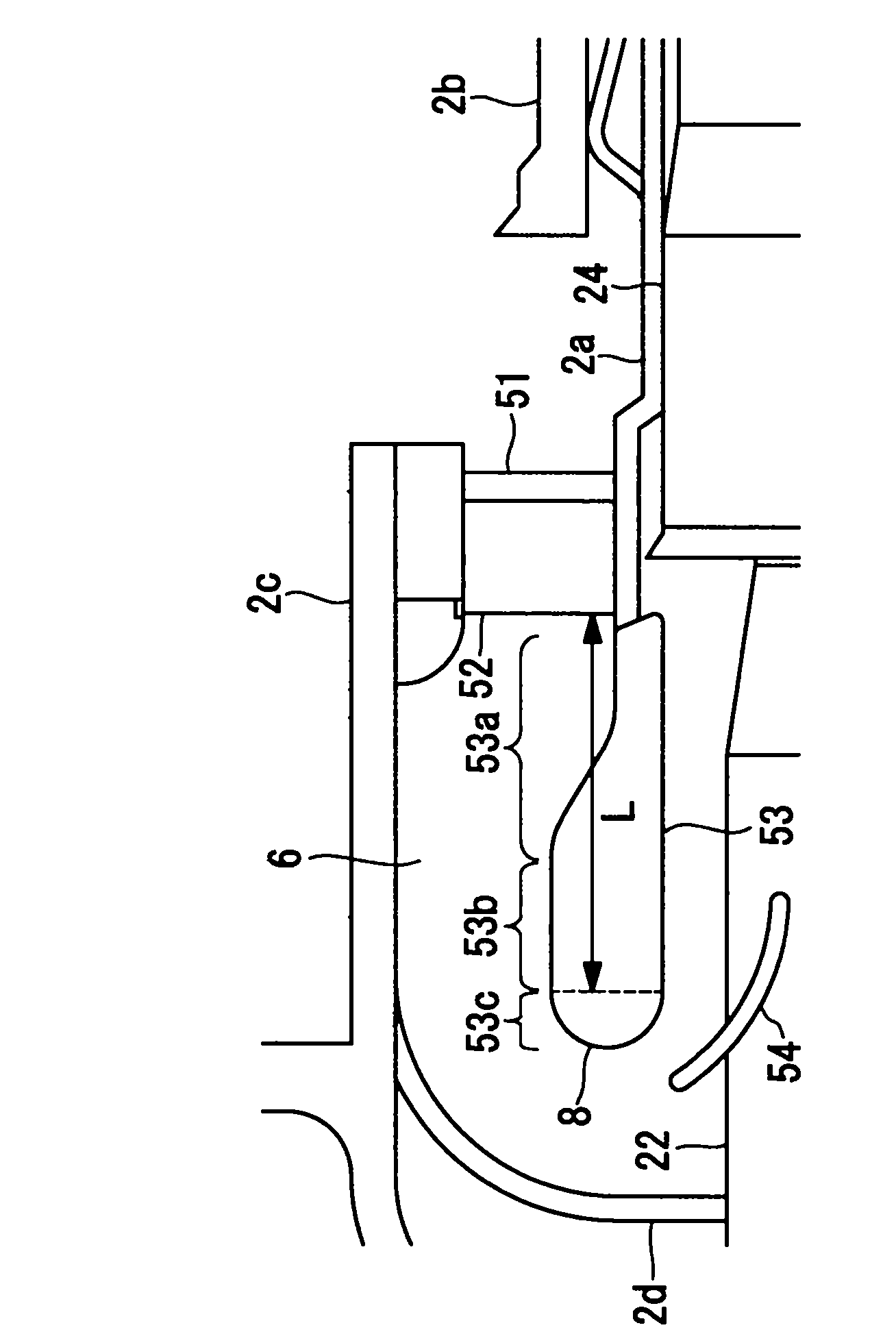
[0045] First, use figure 1 , the burner of the first embodiment will be described. Such as figure 1 As shown, the combustor 1 in this embodiment includes: a pilot nozzle 21 provided along its axis and performing diffusion combustion; The main nozzle 22 of premixed combustion; The guide cone 23 arranged in the mode of covering the front end side of the pilot nozzle 21; The main burner 24 arranged in the mode of covering the front end side of the main nozzle 22; The pilot swirler 25 arranged between the inner walls of the cone 23 ; the main swirler 26 arranged between the outer wall of the main nozzle 22 and the inner wall of the main burner 24 .

[0046] And, the figure 1 The combustor shown is provided with: an inner tube 2a formed substantially coaxially with the pilot nozzle 21 and integrally covering the pilot nozzle 21 and the main nozzle 22; Transition tube 2b that g...

no. 2 approach 〕

[0072] Next, a second embodiment of the present invention will be described. In addition, the overall structure is the same as that of the said 1st Embodiment, The same code|symbol is used for the same structure, and the description is abbreviate|omitted.

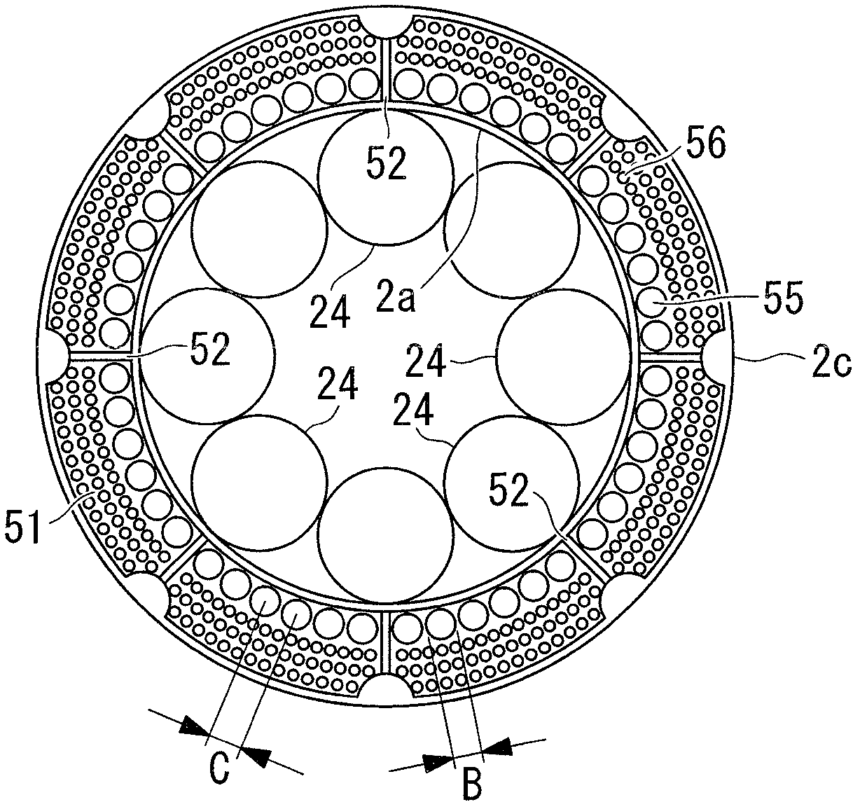
[0073] Figure 5 A partial front view of the rectifying plate 152 of this embodiment is shown in . The rectifying plate 152 of this embodiment is annular, and an outer slit 153 is formed along the outer peripheral edge as a gap with the outer cylinder 2, and an inner slit is formed along the inner peripheral edge as a gap with the inner cylinder 2a. 154. The outer slit 153 and the inner slit 154 are flow passages penetrating the rectifying plate 152 along the axial direction of the flow passage. In addition, rib vicinity slits 155 are respectively provided on the left and right sides of the rib 52 . The rib-near slit 155 is a flow path that penetrates the straightening plate 152 in the axial direction of the flow path, ...

no. 3 approach 〕

[0079] Next, a third embodiment of the present invention will be described. In addition, the overall structure is the same as that of the said 1st Embodiment, The same code|symbol is used for the same structure, and the description is abbreviate|omitted.

[0080] Such as Figure 7 As shown, the top hat nozzle 160 is positioned halfway through a 180 degree turn. The top hat nozzle 160 is a fuel nozzle for premixed combustion in which the top hat fuel gas and compressed air are mixed and combusted on the upstream side compared with the main nozzle 22 for the purpose of reducing NOx. 22 is provided with multiple near the outer peripheral side.

[0081] The inner peripheral portion of the 180-degree turn portion 8 partially has a circular shape in the cross-sectional shape of the burner along the axis as shown in the figure, so that the flow path smoothly changes direction by 180 degrees. The top hat nozzle 160 is a cylinder with a diameter of 10 mm in this embodiment, and is a...


PUM


Abstract

A combustor which is compact and generates a reduced amount of NOx. A combustor (1) is equipped with a pilot nozzle (21) mounted in the axis of the combustor (1) and performing diffusive combustion, main nozzles (22) mounted at circumferentially spaced intervals on the outer peripheral side of the pilot nozzle (21) and performing premixed combustion, an inner tube (2a) surrounding the pilot nozzle (21) and the main nozzles (22), and an outer tube substantially coaxially and externally surrounding the inner tube (2a) and forming a compressed-air flow path (6) between the inner peripheral surface of the outer tube and the outer peripheral surface of the inner tube. The direction of flow of compressed air flowing in the compressed-air flow path (6) is substantially reversed at an end of the inner tube (2a) and introduced into the pilot nozzle (21). A flow rate regulating section is provided in the compressed air flow path (6), and the flow rate regulating section increases the flow rate of the compressed air in that portion of the flow path which is on the inner peripheral side of the combustor (1) to a level greater than the flow rate of the compressed air in that portion of the flow path which is on the outer peripheral side. A flow regulating plate (51) having holes (55, 56) therein can be used as the flow rate regulating section.

Description

technical field [0001] The present invention relates to a combustor of a steam turbine, and more particularly, to a combustor having a structure to reduce deviation and turbulence of the air flow flowing therein. Background technique [0002] For the subject of reducing NOx in a steam turbine combustor, it is very important not to generate a local high fuel concentration by controlling the fuel distribution, and furthermore, it is necessary to make the fuel concentration uniform. Therefore, the increase in the amount of main air through which most of the fuel passes and its homogenization are very important. [0003] Conventionally, there has been disclosed a burner that rotates mainstream air from a vehicle cabin by 180 degrees to guide the mainstream air to a main premixing nozzle (for example, refer to Patent Document 1). In such a burner, in order to eliminate the flow unevenness such as separation accompanying the flow, a rectifying plate is provided at the inlet, and ...

Claims


Application Information

Patent Timeline
Patent Type & Authority Applications(China)
IPC IPC(8): F23R3/10F23R3/26F23R3/28F23R3/32F23R3/34
CPCF23R3/286F23R3/54F23R3/14F23R3/16F23R3/26F23R3/343F23D2900/11402F23R3/10F23R3/28F23R3/32
Inventor 泷口智志汤浅厚志谷村聪
Owner MITSUBISHI POWER LTD
Why Eureka
Try Eureka