Telescopic shifting converter sublance device and using method thereof

A traverse type, converter technology, applied in the direction of manufacturing converters, etc., can solve the problem of no structure of products, and achieve the effect of easy installation and maintenance, wide applicability, and favorable layout and maintenance.

Active Publication Date: 2012-04-25
MCC CAPITAL ENGINEERING & RESEARCH
View PDF4 Cites 11 Cited by
  • Summary
  • Abstract
  • Description
  • Claims
  • Application Information

AI Technical Summary

Problems solved by technology

In order to solve the problems existing in the rotary or transverse converter sub-lance device, the relevant manufacturers have tried their best to find a solution, but no suitable design has been developed for a long time, and the general product has no suitable structure. Able to solve the above problems, this is obviously a problem that the relevant industry is eager to solve

Method used


Image

  • Telescopic shifting converter sublance device and using method thereof
  • Telescopic shifting converter sublance device and using method thereof
  • Telescopic shifting converter sublance device and using method thereof

Examples


Embodiment Construction

[0045] In order to have a clearer understanding of the technical features, purposes and effects of the present invention, the specific implementation manners of the present invention will now be described with reference to the accompanying drawings.

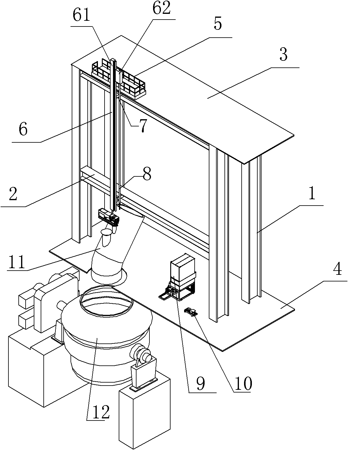
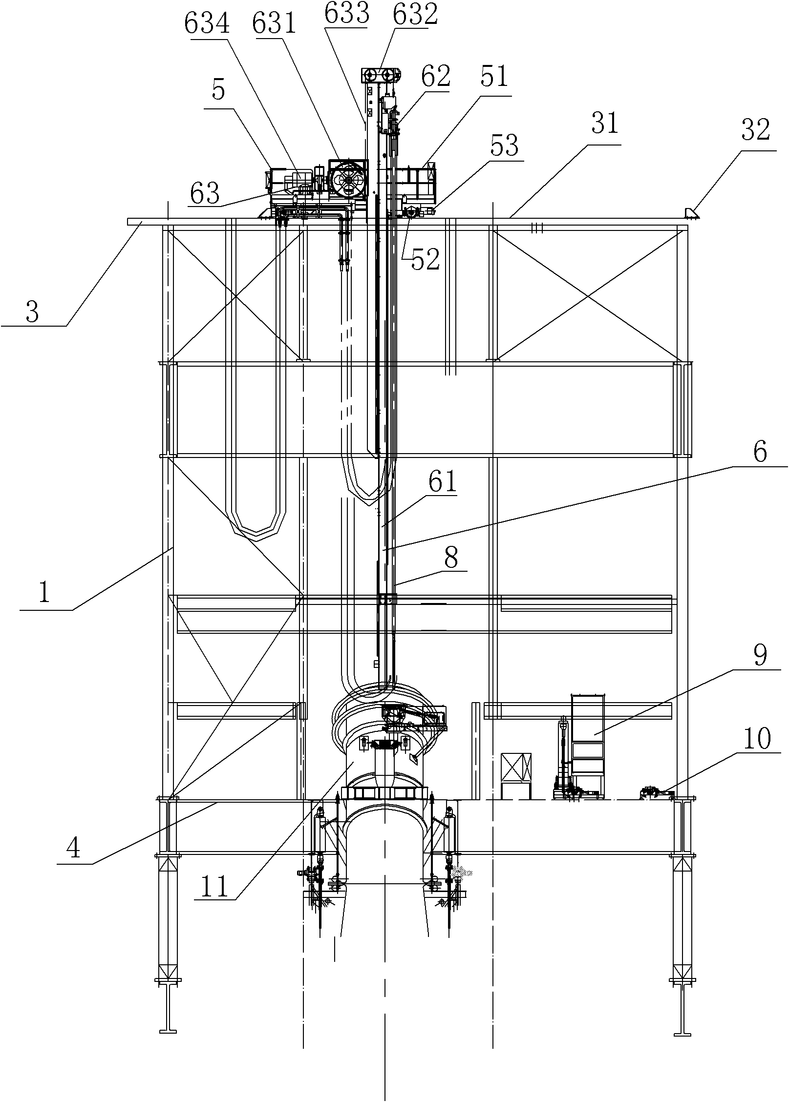
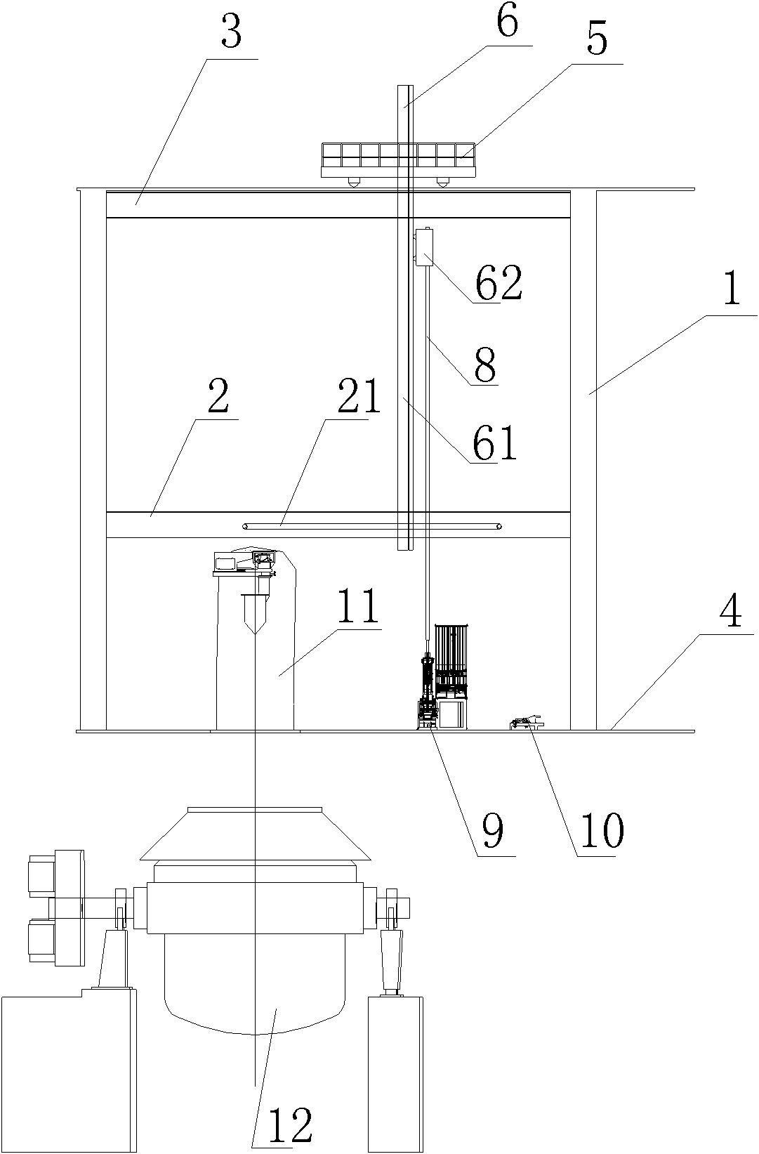
[0046] Please refer to figure 1 , figure 2 , are respectively the three-dimensional structure schematic diagram and the front view structure schematic diagram of the telescopic and transversely moving converter sub-lance device of the present invention. As shown in the figure, the telescopic and laterally moving converter sub-lance device proposed by the present invention is characterized in that the telescopic and laterally moving converter sub-lance device at least includes: a frame, a laterally moving device 5, a lifting device 6 and a telescopic device 7, Wherein the frame is composed of a plurality of longitudinal beams 1 and at least one cross beam 2 , an upper platform 3 is arranged at the upper end of the longitudinal b...


PUM


Abstract

The invention discloses a telescopic shifting converter sublance device and a using method thereof. The telescopic shifting converter sublance device comprises a framework, a shifting device, a lifting device and a telescopic device, wherein the framework consists of longitudinal beams and crossbeams; upper bedplates and lower bedplates are arranged at the upper and lower ends of the longitudinalbeams; the shifting device comprises a shifting trolley; the lifting device comprises a lifting framework, a lifting trolley and a hoisting driving device; a lifting rail is arranged on the side faceof the lifting framework along the longitudinal direction; wheels of the lifting trolley are closely connected with the lifting rail; a sublance is arranged along the longitudinal direction and is fixed on the lifting trolley; the lifting trolley moves along the lifting rail through the hoisting driving device; and the telescopic device at least comprises a first hydraulic driving cylinder to drive the telescopic movement of the lifting framework. The telescopic shifting converter sublance device is simple in structure, light in weight, high in strength and rigidity, and high in dynamic stability and dynamic responsiveness, and is easy to mount and maintain; and through telescopic and shifting actions, a converter sublance measurement position, an upper probe position and a maintenance position are switched.

Description

technical field [0001] The invention relates to a converter sub-lance technology in the iron and steel metallurgy industry, in particular to a telescopic and laterally moving converter sub-lance device and a use method for large and medium-sized converters. Background technique [0002] As we all know, the converter sub-lance is used to obtain actual data from the converter during the molten steel smelting process, which can detect the molten steel pool and solidification temperature, oxygen content and molten pool liquid level height, etc. The BOF sublance enables molten steel sampling while the BOF is in an upright position without interrupting the oxygen blowing process. Since the sub-lance of the converter can ensure the continuous progress of the smelting process, it is of great benefit to maintain the stability of the process. [0003] At present, most of the action modes of sub-gun devices commonly used in the iron and steel metallurgy industry are rotary or lateral....

Claims


Application Information

Patent Timeline
Patent Type & Authority Applications(China)
IPC IPC(8): C21C5/46
Inventor 常海张茂林
Owner MCC CAPITAL ENGINEERING & RESEARCH
Why Eureka
Try Eureka