Multifunctional urban road cleaning vehicle

A multifunctional, cleaning vehicle technology, applied in road cleaning, snow cleaning, construction, etc., can solve the problems of single function, complex structure, expensive price, etc., and achieve the effect of simple and flexible operation, simple and reasonable structure, and wide application range

Inactive Publication Date: 2012-04-25
刘和平
6 Cites 7 Cited by

AI-Extracted Technical Summary

Problems solved by technology

As far as the relevant garbage cleaning vehicles shown on the market and reported by related materials are concerned, although the cleaning efficiency of garbage has been relatively improved, its structure is...

Abstract

The invention discloses a multifunctional urban road cleaning vehicle. The multifunctional urban road cleaning vehicle consists of a front vehicle body and a back vehicle body, wherein the front vehicle body comprises a sweeping mechanism, a walking mechanism and a rubbish-collecting mechanism; the back vehicle body comprises a seat and man-powered walking mechanism; the sweeping mechanism is a front brush frame which is hinged with the front vehicle body; a balancing beam is arranged on the front brush frame; rotator supporting bases are hinged on the lower parts of two ends of the balancing beam through bevel gears respectively; rotators with cleaning brushes are arranged on the lower parts of the supporting bases; the rotators are driven by a clutch and speed-increasing big chain wheels; the walking mechanism comprises an accumulator on the back vehicle body; small chain wheels are arranged on the accumulator and the motor output shaft; the small chain wheels are connected with the big chain wheels on a back axle through chains; the rubbish-collecting mechanism comprises a collecting frame and sweeping and collecting roller brushes; two sweeping and collecting roller brushes are transversely arranged on the collecting frame in parallel; through the opposite rotation of the sweeping and collecting roller brushes, rubbish is thrown into a rubbish box through an arc hood; the seat and man-powered walking mechanism comprises a vehicle frame; a man-powered pedal and wheels are arranged on the vehicle frame; and the front end of the vehicle frame is hinged with the front vehicle body.

Application Domain

Technology Topic

Image

  • Multifunctional urban road cleaning vehicle
  • Multifunctional urban road cleaning vehicle
  • Multifunctional urban road cleaning vehicle

Examples

  • Experimental program(2)

Example Embodiment

[0018] Example 1
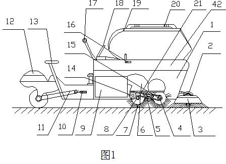
[0019] Depend on Figure 1-4 As shown, 1 in the figure is the front car body of the car body, the front car body 1 includes a cleaning mechanism, a walking mechanism, and a garbage collection mechanism, and the rear car body includes a battery 38, a seat and a human walking mechanism;
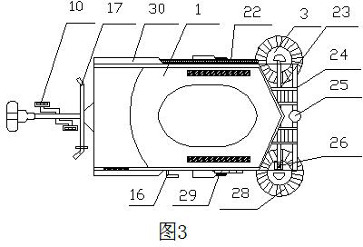
[0020] The cleaning mechanism includes: a front brush frame 24 hinged with the front end of the front vehicle body 1 and a rotating body 3 with a cleaning brush, a balance beam 23 is provided on the front brush frame 24, and the lower parts of the two ends of the balance beam 23 pass through the bevel gears 2 respectively. A rotating body support base 31 is hinged, and the rotating body 3 with a cleaning brush is fixed on the lower part of the rotating body support base 31; a clutch 26 is provided on the balance beam 23, and the flywheel 43 of the clutch 26 travels with the front vehicle body through the chain 44 The speed increasing sprocket 27 on the main shaft 47 of the wheel 29 is connected; a support wheel 25 is also arranged in the middle of the front brush holder 24; The front end of the rod 18 is hinged with the front brush holder 24 through the pull wire 51, the chain 41 and the guide wheel 40;
[0021] The traveling mechanism includes a battery 38 on the rear body 34, and a sprocket 37 is provided on the battery 38 and the motor output shaft. The sprocket 37 is connected with the large sprocket 36 provided on the rear wheel 35 shaft through the chain 11;
[0022] Garbage collection mechanism: a collection rack is arranged at the lower part of the front car body 1, and two cleaning and collecting roller brushes 7 arranged in parallel and transversely are arranged on the collecting rack near the cleaning mechanism. There is a clutch 54 on the clutch 54, and the sprocket 45 is connected with the speed-increasing sprocket 48 on the main wheel 47 of the front vehicle body 1 through the chain 46, and a fixed chain is also provided on the collecting rack. The fixed sprocket mechanism includes: the guide sprocket 14 is connected with the driving sprocket 15 on the driving shaft 4 of the cleaning and collecting roller brushes through the chain 5, and the driven sprocket 8 on the driven shaft 21 of the cleaning and collecting roller brushes It engages with the external teeth of the chain 5, and forms two parallel and horizontally arranged cleaning and collecting roller brushes 7 to rotate in opposite directions; an arc for throwing garbage is also provided on the upper part of the two parallel and horizontally arranged cleaning and collecting roller brushes 7. The discharge port at the rear end of the arc-shaped shroud 6 corresponds to the entrance of the garbage box 9; the upper part of the front vehicle body 1 is also provided with a main garbage storage box 42, which is the main garbage storage box 42. The cover 19 is provided on the upper part of the main garbage storage box.
[0023] The seat and the human-powered walking mechanism include a frame and a saddle 13 arranged on the rear body 34, a human-powered pedal 10 and a traveling wheel 35 are arranged at the lower part of the frame, and the saddle 13 is arranged on the rear upper part of the frame; The front end is also provided with a steering shaft 39 that is hinged with the front vehicle body, and the steering shaft 39 is also provided with a grease nipple for lubrication.
[0024] In order to facilitate the operator to access the garbage in the garbage container 9, a garbage container door 32 is also provided on the side of the front vehicle body 1, and a garbage container door handle 33 is provided on the garbage container door 32. figure 1 20 is the door handle of the garbage main storage box door, and a support frame handle 16 of the garbage main storage box is also provided on the side of the front body 1, open the garbage main storage box door 19, and rotate the support frame handle 16 90 degrees , then the upper garbage main storage box door 19 is fixed and supported to open, so that after the garbage in the garbage box 9 is filled, it can be poured into the garbage main storage box 42, or the larger garbage and net-shaped garbage. , directly put it into the main garbage storage box 42 ; a partition 30 for storing the shovel 22 is provided on the side wall of the front vehicle body 1 .
[0025] In addition, the structure also includes a tool box 12 and a braking device controlled by the operation control handlebar 17. 49 in the figure is the hinged part of the chain 50 and the front brush frame 24; The clutch flywheel 43 on the balance beam 23 is disengaged from the clutch 26, and the cleaning brush 28 does not rotate in this state. At the same time, the clutch flywheel 53 on the driving shaft 4 for cleaning and collecting the roller brush is also disengaged from the clutch 54. In this state, the cleaning The collecting roller brush 7 does not rotate, which is convenient for energy saving and labor saving.
[0026] When the battery is out of power or the machine needs manual work, a driven shaft 55 is provided on the traveling wheel 35 of the rear vehicle body 34, and a large sprocket 36 is set on the driven shaft 55. The small sprocket 37 is connected to the large sprocket 36 on the rear car body through the chain 11, and the cleaning car moves forward by stepping on the manpower pedal 10 to realize the speed reduction and increase torque.
[0027] Cleaning work procedure:
[0028] First open the electric lock on the operation control handlebar 17, the battery 38 starts to start, and manually control the front brush holder lifting push rod 18. The racks 24 are hinged, the front brush rack 24 moves down toward the ground, and the cleaning side brushes 28 are in contact with the ground; the rotating cleaning force is adjusted according to the road surface conditions and the difficulty of cleaning.
[0029]When the cleaning vehicle moves forward, the cleaned garbage collects between the two cleaning brushes 28 in a ridge-like shape and enters the garbage collection part provided at the lower part of the front vehicle body 1 , and passes through the two collection racks in the front vehicle body 1 . The operation of the cleaning and collecting roller brush 7 and the fixed sprocket mechanism enables the garbage to be collected, and the collected garbage is thrown into the specific curved surface cover 6 in the machine, so that the collected garbage is thrown to a high position and enters the garbage. The box entrance is completed, and the cleaning program is completed.

Example Embodiment

[0030] Example 2
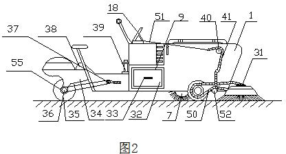
[0031] like Figure 5 As shown, the snow removal mechanism includes a snow removal frame 102 that is hinged with the front end of the front vehicle body 1, a snow removal board 101 is provided at the front end of the snow removal frame 102, and a snow removal frame hinge 103 is provided at the rear end of the snow removal frame 102. The frame 102 is provided with a hinge hole 104 connected with the chain 41 .
[0032] In the case of stacking work, or when it snows and freezes in winter, the front brush holder 24 is removed from the front vehicle body 1, and then the hinge part 103 of the snow removal frame is connected to the front vehicle at the hinge part 49 at the front end of the front vehicle body 1. At the same time, push the front brush holder lifting push rod 18 on the front vehicle body, the front end of the front brush holder lifting push rod 18 is connected with the hinged part 103 of the snow board through the pull wire 51, the chain 41 and the guide wheel 40. Articulated, so that the snow removal board 101 floats on the road and enters the working state, thereby playing the role of removing snow;
[0033] The cleaning operation of urban roads is affected by seasonal changes, which makes the cleaning operation uncertain; for example, after the autumn rain, the wind blows the leaves and sticks to the road surface, which makes cleaning more difficult. It is an effective supplement to the unconventional operation for the accumulation wiping and snow removal operations of this vehicle. The power device of this cleaning vehicle is the battery 38, which can also be a gas oil or diesel engine.

PUM

no PUM

Description & Claims & Application Information

We can also present the details of the Description, Claims and Application information to help users get a comprehensive understanding of the technical details of the patent, such as background art, summary of invention, brief description of drawings, description of embodiments, and other original content. On the other hand, users can also determine the specific scope of protection of the technology through the list of claims; as well as understand the changes in the life cycle of the technology with the presentation of the patent timeline. Login to view more.

Similar technology patents

High-efficient engine

InactiveCN1362575ASimple and reasonable structureIncrease power and efficiencyReciprocating piston enginesClutchPiston rod
Owner:訾应举

Impeller structure of centrifugal lampblack filter

InactiveCN101566174ASimple and reasonable structureThe manufacturing process is simple and reasonableDomestic stoves or rangesPump componentsImpellerAir volume
Owner:NINGBO FOTILE KITCHEN WARE CO LTD

Classification and recommendation of technical efficacy words

  • Simple and flexible operation
  • Simple and reasonable structure

Processing method of local laser blackening for coating metalwork

Owner:SHANGHAI INST OF TECHNICAL PHYSICS - CHINESE ACAD OF SCI

Microcrystalline wax hydrogenation method

ActiveCN102311803AShort processSimple and flexible operationPetroleum wax refiningMicrocrystalline waxHigh pressure
Owner:CHINA PETROLEUM & CHEM CORP +1

Live broadcast method and device

Owner:VISIONVERA INFORMATION TECH CO LTD
Why Eureka
Try Eureka