Mechanical cipher lock

A technology of mechanical combination lock and combination wheel, which is applied in the field of mechanical combination locks to achieve the effect of preventing being spied on and having a good application prospect

Active Publication Date: 2012-04-25
HANGZHOU HUOER TECH
View PDF9 Cites 2 Cited by
  • Summary
  • Abstract
  • Description
  • Claims
  • Application Information

AI Technical Summary

Problems solved by technology

Although this kind of lock has effectively increased the amount of codes to a certain extent, combining mechanical locks and coded locks, the codes are still detectable.

Method used


Image

  • Mechanical cipher lock
  • Mechanical cipher lock
  • Mechanical cipher lock

Examples


Embodiment 1

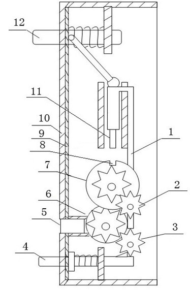
[0036] A mechanical combination lock, such as Figures 1 to 3 Shown: including shell 10 and code wheel 7, there are 6 code wheels 7, the number can be increased or decreased according to actual requirements, code wheel 7 is provided with code modification wheel 2, code modification wheel 2 is provided with display wheel 6, code Between the wheel 7 and the password modification wheel 2, between the password modification wheel 2 and the display wheel 6 through gear meshing, the inner wall of the housing 10 is provided with an isolation layer 9, and the isolation layer 9 is bonded to the inner wall of the housing 10 to prevent ultrasonic detection or radiation detection , the housing 10 is provided with an input device 4 and an opening button 12, the input device 4 is an input button, including a button and a spring, the spring is arranged between the splint parallel to the housing 10 and the housing 10, and the spring is fixed on the button, The opening button 12 is provided wit...

Embodiment 2

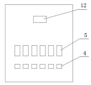
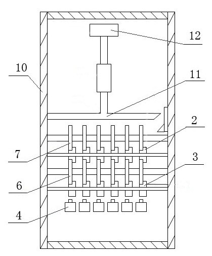
[0038] A mechanical combination lock, such as Figures 4 to 6Shown: including shell 10 and code wheel 7, there are 6 code wheels, the number can be increased or decreased according to actual requirements, code wheel 7 is provided with display wheel 6, code wheel 7 and display wheel 6 are coaxial and can rotate with each other , the housing 10 is provided with an input device 4 and an opening button 12, the input device 4 is an input button, including a button and a spring, the spring is arranged between the splint parallel to the housing 10 and the housing 10, and the spring is fixed on the button, The opening button 12 is provided with a stop connecting rod 1 and a moving latch rod 11, and the opening button 12 is hingedly connected with the moving latch rod 11 and the stopping connecting rod 1 respectively. The input device 4 is provided with a connecting wheel 3, and the end of the button Connected with the connecting wheel 3, the password wheel 7 is provided with a groove ...

Embodiment 3

[0040] A mechanical combination lock, such as Figures 7 to 9 Shown: including shell 10 and code wheel 7, there are 6 code wheels 7, the number can be increased or decreased according to actual requirements, shell 10 is provided with input device 4 and open button 12, input device 4 is an input rotary disk, input rotary There are digital scales and stop slots on the disk, and the opening button 12 is provided with a stop link 1 and a moving latch lever 11. 7 is provided with groove 8, and moving latch bar 11 cooperates with groove 8. When unlocking, first input the password on the input device 4, then press the opening button 12, the opening button 12 drives the stop connecting rod 1 and the moving latch bar 11 to move downward together, before the moving latch bar 11 reaches the groove 8, The stop connecting rod 1 enters the stop slot, so that the input rotary disk can no longer rotate, and then the moving latch bar 11 reaches the groove 8. If the code is correct, that is, t...


PUM


Abstract

The invention relates to a mechanical cipher lock which comprises a shell (10) and a cipher wheel (7), wherein an input device (4) and an opening button (12) are arranged on the shell (10); a stopping connection rod (1) is arranged on the opening button (12); a movable latch rod (11) is arranged on the opening button (12); a groove (8) is formed on the cipher wheel (7); and the movable latch rod (11) is matched with the groove (8). A cipher input part and a cipher information part are separated, so that the cipher can not be compared when the cipher is input, and the cipher can not be input when the cipher is compared, thereby really achieving the purpose that the cipher can not be stolen. The mechanical cipher lock provided by the invention has excellent application prospects in the aspects of emergency opening mechanisms of mechanical cipher lock devices and electronic locks, and the like.

Description

technical field [0001] The invention relates to a mechanical combination lock. Background technique [0002] The insecurity of mechanical locks is mainly due to the physical characteristics of the password information of mechanical locks, and the password information part of almost all existing mechanical lock designs can be detected, resulting in no guarantee of security. [0003] Ordinary anti-theft door locks use a cross-lock chip, and the pins are exposed in the hole, which can be detected by a simple method; the dial-type combination lock for safes uses a multi-segment card slot mode, and the lock lever will move after alignment to bring the most obvious physical The feature is sound, which allows criminals to take advantage of this feature and easily complete password cracking; the input part of the mechanical combination lock is exposed outside, and the password information is easily recorded by a high-power camera; what’s more, it uses a ray scanning structure to To...

Claims


Application Information

Patent Timeline
Patent Type & Authority Applications(China)
IPC IPC(8): E05B37/20E05B1/00E05B17/22
Inventor 郎孙俊
Owner HANGZHOU HUOER TECH
Why Eureka
Try Eureka