Embedded oil charging structure for high-pressure fuel oil system

A high-pressure fuel, embedded technology, applied in the charging system, fuel injection device, engine components, etc., can solve the problems of injection pressure drop, injection delay increase, control accuracy reduction, etc., to achieve smooth oil return, easy installation, short The effect of high pressure oil pipe

Inactive Publication Date: 2012-04-25
CHINA NORTH IND GRP NO 70 RES INST
View PDF6 Cites 12 Cited by
  • Summary
  • Abstract
  • Description
  • Claims
  • Application Information

AI Technical Summary

Problems solved by technology

For diesel engines using electronically controlled fuel injection systems, if the top oil inlet structure is still used, the high-pressure volume and flow resistance will increase, resulting in a drop in injection pressure, an increase in injection delay, and a decrease in control accuracy. The advantages of high-pressure injection and quick response cannot be fully utilized. Affect the configuration performance

Method used


Image

  • Embedded oil charging structure for high-pressure fuel oil system
  • Embedded oil charging structure for high-pressure fuel oil system

Examples


Embodiment Construction

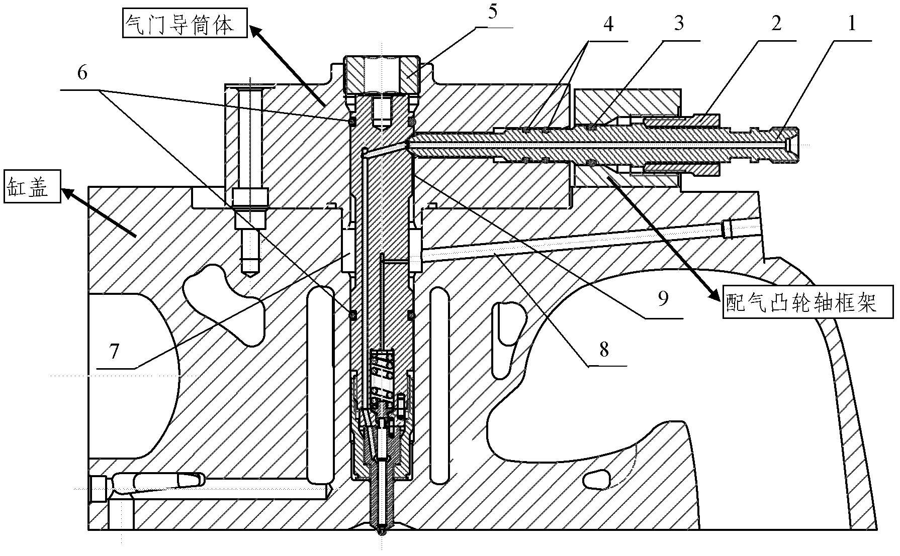
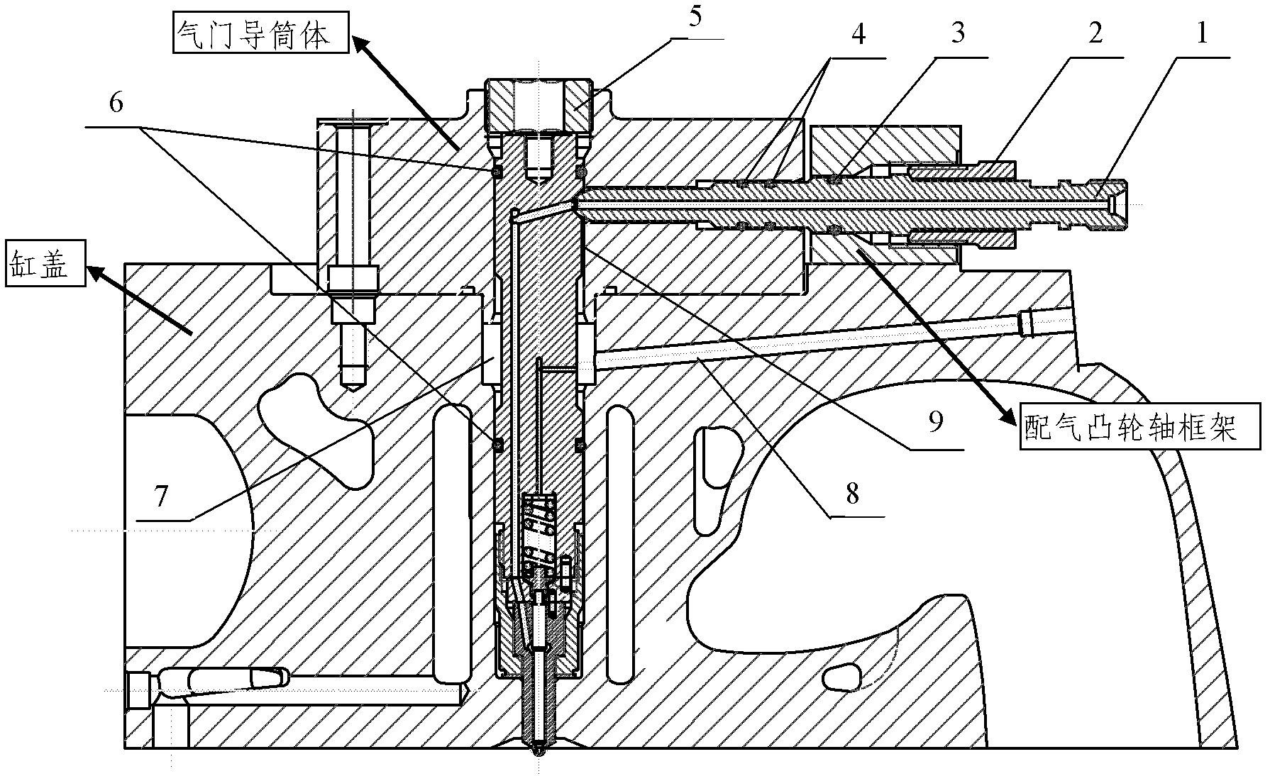
[0009] An embedded oil inlet structure of a high-pressure fuel system, the related components include a side oil inlet pipe 1, a side compression nut 2, a top compression nut 5, an O-ring seal 3, an O-ring seal 4, an O-ring seal The ring 6 is characterized in that the lateral oil inlet pipe 1 is embedded in the frame of the distribution camshaft and the valve guide cylinder; Press the lateral oil inlet pipe 1 against the side wall of the fuel injector with the compression nut 2, and tighten the lateral compression nut 2 on the frame of the gas distribution camshaft; use the top compression nut 5 to compress the fuel injector assembly In the inner hole of the cylinder head, the top compression nut 5 is tightened on the valve guide cylinder body; two O-rings 4 are arranged in cooperation with the side oil inlet pipe 1 and the valve guide cylinder body, and the side oil inlet pipe 1 is connected with the valve camshaft An O-ring seal 3 is arranged on the frame, and an O-ring 6 is...


PUM


Abstract

The invention discloses an embedded oil charging structure for a high-pressure fuel oil system. A lateral oil charging pipe is transversely embedded into a gas distribution camshaft frame and an air valve guide barrel; an oil sprayer is vertically arranged in a cylinder cover and the air valve guide barrel, and is used for charging oil laterally; a lateral oil charging pipe is pressed tightly onto the side wall of the oil sprayer by adopting a lateral compression nut, and is screwed on the gas distribution camshaft frame; an oil sprayer assembly is pressed tightly into a cylinder cover inner hole by adopting a top end compression nut, and is screwed on the air valve guide barrel; two O-shaped sealing rings are distributed on the lateral oil charging pipe and the air valve guide barrel in a matching way; an O-shaped sealing ring is distributed on the lateral oil charging pipe and the gas distribution camshaft frame in a matching way; an O-shaped sealing ring is distributed on the oil sprayer, the air valve guide barrel and the cylinder cover respectively in a matching way; an oil return cavity is communicated with a phi5 oil return channel on the cylinder cover; and an oil leaking groove is formed between the oil charging conical surface of the oil sprayer and the oil return cavity. Due to the adoption of the embedded oil charging structure, a shorter high-pressure oil pipe is realized, the sealing requirements of fuel oil and lubricating oil can be met simultaneously, oil return of the oil sprayer is smooth, and the entire structure is easy to install.

Description

technical field [0001] The invention belongs to the technical field of power machinery, and in particular relates to an embedded fuel inlet structure of a high-pressure fuel system. Background technique [0002] For diesel engines using electronically controlled fuel injection systems, how to shorten the length of the high-pressure oil circuit while meeting the sealing requirements of fuel and lubricating oil is a technical difficulty. [0003] Conventional in-line pump fuel injection system generally adopts the oil inlet structure at the top of the injector. The high-pressure fuel pipe bypasses the valve chamber cover to connect to the fuel injector, and the nut of the fuel pipe joint directly presses the cone head of the high-pressure fuel pipe and the sealing matching cone surface of the fuel injector. The structure has fewer components and is easy to process, but the length of the oil pipe is longer and there are many bent parts of the oil passage. For diesel engines us...

Claims


Application Information

Patent Timeline
Patent Type & Authority Applications(China)
IPC IPC(8): F02M55/00F02M61/16
Inventor 郭海洲王增全高青秀姜伟
Owner CHINA NORTH IND GRP NO 70 RES INST
Why Eureka
Try Eureka