Pressure balance valve for liquid flow battery

A liquid flow battery and balance valve technology, applied in the direction of balance valves, fuel cells, fuel cell additives, etc., can solve problems such as blockage of battery stack flow channels, unusable applications, and polluted electrolytes, and achieve stable charge and discharge performance and extended battery life. Battery life, the effect of improving battery performance

Inactive Publication Date: 2017-05-31
SUZHOU JIURUN ENERGY TECH
View PDF4 Cites 2 Cited by
  • Summary
  • Abstract
  • Description
  • Claims
  • Application Information

AI Technical Summary

Problems solved by technology

However, the pressure balance valve is mainly used to decompress and balance the outlet pressure, and cannot realize the real-time pressure balance between the two pipelines. The pressure stabilizing valve generally has a complicated structure and high cost, and usually cannot be used in high-temperature acidic environments.
The structure of the patent CN201010604524.3 is mainly used for cold and hot water pressure balance,

Method used


Image

  • Pressure balance valve for liquid flow battery
  • Pressure balance valve for liquid flow battery
  • Pressure balance valve for liquid flow battery

Examples


Example Embodiment

[0030] Example 1

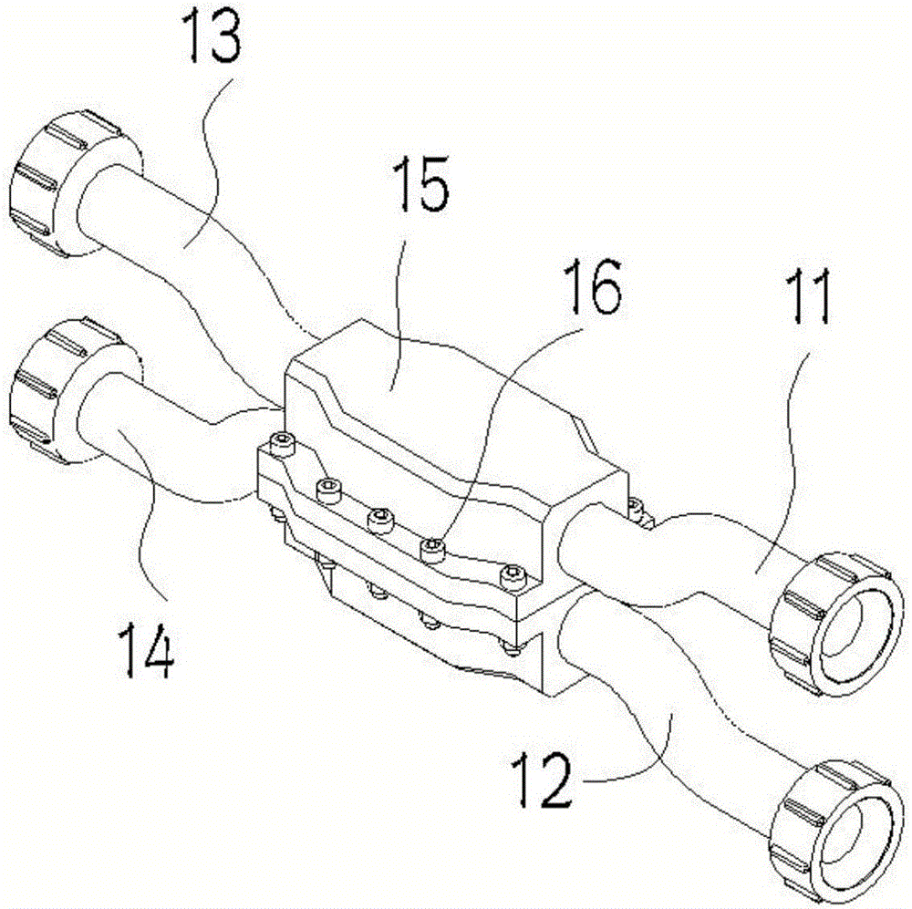
[0031] like figure 1 The shown pressure balance valve for the flow battery includes two symmetrically arranged valve bodies 15, which are connected by fasteners 16; the valve bodies 15 each have a chamber, respectively a positive electrode pressure balance chamber 221a and a negative electrode pressure balance chamber 221a. Chamber 221b, the openings of the two chambers 221a and 221b are arranged oppositely; the electrolyte flow channel, which is arranged on the two ends of the chamber, respectively includes the positive electrolyte inlet 11 and the positive electrolyte on the two ends of a chamber. outlet 13, and the negative electrode electrolyte inlet 12 and the negative electrode electrolyte outlet 14 that are arranged on the two ends of the other chamber, and the positive electrode electrolyte inlet 11 and the negative electrode electrolyte inlet 12 are respectively positioned on the same side of the valve body, and the The positive electrode electroly...

Example Embodiment

[0034] Example 2

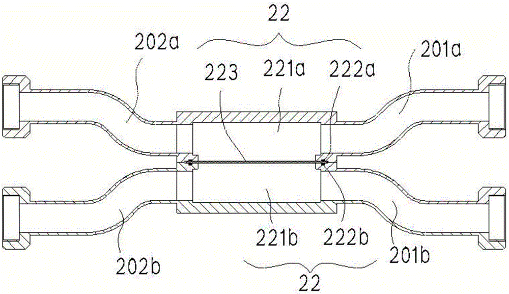
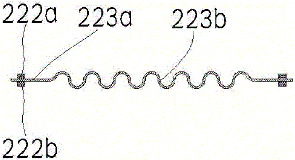
[0035] like figure 2The pressure balance valve for the flow battery with the structure shown, from the cross-section of the pressure balance valve 20 for the flow battery, includes two symmetrically arranged valve bodies 22, which are connected by fasteners; the two valve bodies respectively have a positive electrode balance The chamber 221a and the negative balance chamber 221b, the openings of the two balance chambers 221a and 221b are arranged oppositely; The positive electrode electrolyte solution inlet 201a and the positive electrode electrolyte solution outlet 202a at both ends of 221a, and the negative electrode electrolyte solution inlet 201b and the negative electrode electrolyte solution outlet 202b arranged at both ends of the negative electrode balance chamber 221b, and the positive electrode electrolyte solution inlet 201a and the negative electrode Electrolyte inlet 201b is respectively positioned on the same side of the two valve bodies 22, ...


PUM

PropertyMeasurementUnit
Thicknessaaaaaaaaaa

Abstract

The invention discloses a pressure balance valve for a liquid flow battery. The pressure balance valve comprises two symmetrically-arranged valve bodies, electrolyte flow channels and a flexible diaphragm; each of the valve bodies is provided with an opening-shaped chamber, and openings of the two chambers are symmetrically formed; the electrolyte flow channels respectively comprise a positive electrolyte inlet and a positive electrolyte outlet formed in the two end sides of one chamber as well as a negative electrolyte inlet and a negative electrolyte outlet formed in the two end sides of the other chamber, and each of the electrolyte flow channels is formed in the two end sides of the corresponding chamber; the flexible diaphragm is hermetically arranged between the two valve bodies to perform closed isolation on the oppositely-formed chambers. The pressure balance valve for the liquid flow battery, disclosed by the invention, is simple in structure, feasible in process, convenient to mount, stable in performance and low in cost, and can effectively improve the running safety of the liquid flow battery, ensure the stable and reliable function of the liquid flow battery and prolong the service life of the liquid flow battery.

Description

technical field [0001] The invention belongs to the technical field of electrochemical liquid flow batteries, and in particular relates to a pressure balance valve for a liquid flow battery. Background technique [0002] The liquid flow battery realizes the storage function through the price change of the reactive material, that is, the charging and discharging of the battery is realized by the way that the charge passes through the electrolyte diaphragm between the positive and negative electrodes. The electrolyte diaphragm is a polymer functional membrane with ion selective permeation. The material properties of the diaphragm require that the pressure difference of the fluid passing through the two sides of the diaphragm cannot exceed a certain value, and the pressure of the fluid flowing through the two sides of the diaphragm needs to be balanced. After the pressure balance valve is added, the inlet pressure of the battery electrolyte can be effectively balanced, the pres...

Claims


Application Information

Patent Timeline
IPC IPC(8): H01M8/04276H01M8/04746F16K17/24
CPCF16K17/24H01M8/04276H01M8/04783Y02E60/50
Inventor 马志啟谭长永王聪康田清
Owner SUZHOU JIURUN ENERGY TECH
Why Eureka
Try Eureka